| Last Modified: 7-3-2017 | 6.8:8.0.40 | Doc ID: RM0000018NI004X |
| Model Year Start: 2007 | Model: LX470 | Prod Date Range: [08/2006 - ] |
| Title: AIR CONDITIONING: AIR CONDITIONING SYSTEM: Blower Motor Circuit; 2007 MY LX470 [08/2006 - ] | ||
|
Blower Motor Circuit |
DESCRIPTION
This is the power source for the blower motor.
WIRING DIAGRAM
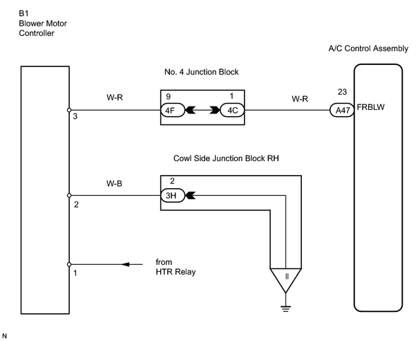
INSPECTION PROCEDURE
PROCEDURE
|
1. |
CHECK AIR CONDITIONING AMPLIFIER |
|
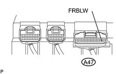
(a) Remove the A/C amplifier with the connector still connected. (b) Turn the ignition switch ON. (c) Operate the blower motor. (d) Measure the voltage between terminal FRBLW (A47-23) of the A/C amplifier and body ground. Standard voltage: 10 to 14 V |
|
| OK |

|
PROCEED TO NEXT CIRCUIT INSPECTION SHOWN ON PROBLEM SYMPTOMS TABLE |
|

|
2. |
CHECK BLOWER MOTOR |
|
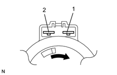
(a) Remove the blower motor. (b) Connect the positive (+) lead from the battery to terminal 2 of the blower motor connector and the negative (-) lead to terminal 1, and check the blower motor. OK: Blower motor operates smoothly. |
|
| NG |
|
|
|
3. |
CHECK BLOWER MOTOR CONTROLLER |
|
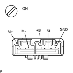
(a) Remove the blower motor controller with the connectors still connected. (b) Turn the ignition switch ON. (c) Operate the blower motor (High blower speed). OK:
|
|
| NG |
|
| OK |
|

|

|