| Last Modified: 7-3-2017 | 6.8:8.0.40 | Doc ID: RM0000018O6006X |
| Model Year Start: 2007 | Model: LX470 | Prod Date Range: [08/2006 - ] |
| Title: POWER STEERING: POWER STEERING GEAR: DISASSEMBLY; 2007 MY LX470 [08/2006 - ] | ||
DISASSEMBLY
NOTICE:
When using a vise, do not overtighten it.
|
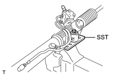
1. FIX POWER STEERING GEAR ASSEMBLY (a) Using SST, fix the gear assembly in a vise, as shown in the illustration. SST: 09630-00014 09631-00142 |
|
|
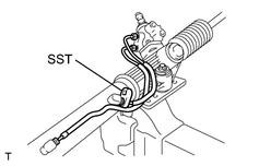
2. REMOVE TURN PRESSURE TUBE ASSEMBLY (a) Using SST, remove the 2 tubes. SST: 09023-38201 |
|
|
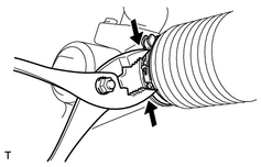
3. REMOVE CLIP, RACK BOOT AND CLAMP (a) Using pliers, loosen the clamp, as shown in the illustration. NOTICE: Be careful not to damage the boot. (b) Remove the clip, rack boot and clamp. (c) Use the same procedure described above for the other side. HINT: Mark the RH and LH rack boots. |
|
4. REMOVE STEERING RACK END
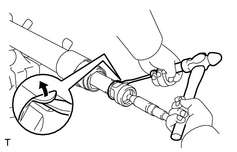
(a) Using a screwdriver and hammer, shake back the washer.
NOTICE:
Avoid any impact to the steering rack.
|
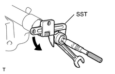
(b) Using a spanner to hold the steering rack steady, and using SST, remove the rack end. SST: 09922-10010 NOTICE: Use SST 09922-10010 in the direction shown in the illustration. |
|
(c) Remove the claw washer.
(d) Use the same procedure described above for the other side.
HINT:
Mark the RH and LH rack boots.
|
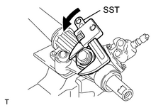
5. REMOVE RACK GUIDE SPRING CAP LOCK NUT (a) Using SST, remove the lock nut. SST: 09922-10010 NOTICE: Use SST 09922-10010 in the direction shown in the illustration. |
|
6. REMOVE RACK GUIDE SPRING CAP
7. REMOVE RACK GUIDE SPRING AND RACK GUIDE SUB-ASSEMBLY
8. REMOVE DUST COVER
|
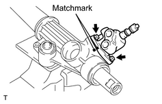
9. REMOVE CONTROL VALVE HOUSING WITH CONTROL VALVE ASSEMBLY (a) Place matchmarks on the valve housing and rack housing. (b) Remove the 2 bolts. (c) Pull out the control valve assembly with the valve housing. (d) Remove the O-ring from the valve housing. |
|
10. REMOVE CONTROL VALVE ASSEMBLY
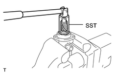
(a) Using SST, loosen the bearing guide nut.
SST: 09631-20060
|
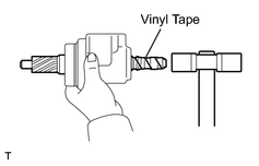
(b) Wind vinyl tape to the control valve shaft. |
|
(c) Using a plastic hammer, tap out the valve assembly with the nut from the control valve housing.
NOTICE:
Be careful not to damage the oil seal lip.
(d) Remove the nut from the valve assembly.
NOTICE:
Be careful not to damage the oil seal lip.
(e) Remove the O-ring from the nut.
|
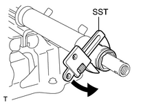
11. REMOVE CYLINDER END STOPPER AND SPACER (a) Using SST, remove the stopper. SST: 09922-10010 NOTICE: Use SST 09922-10010 in the direction shown in the illustration. (b) Remove the O-ring from the stopper. |
|
|
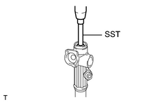
12. REMOVE STEERING RACK AND OIL SEAL (a) Using SST, press out the rack and oil seal. NOTICE: Take care not to drop the rack. SST: 09950-70010 09951-07200 (b) Remove the oil seal from the rack. |
|

|

|