| Last Modified: 7-3-2017 | 6.8:8.0.40 | Doc ID: RM0000018RH005X |
| Model Year Start: 2007 | Model: LX470 | Prod Date Range: [08/2006 - ] |
| Title: DRIVE SHAFT: FRONT DRIVE SHAFT: REMOVAL; 2007 MY LX470 [08/2006 - ] | ||
REMOVAL
HINT:
- Use the same procedures for the RH side and LH side.
- The procedures listed below are for the LH side.
1. REMOVE FRONT WHEEL
Torque:
131 N·m {1,340 kgf·cm, 97ft·lbf}
|
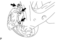
2. REMOVE FRONT DISC BRAKE CYLINDER ASSEMBLY (a) Remove the bolt and disconnect the flexible hose from the steering knuckle. Torque: 28 N·m {290 kgf·cm, 21ft·lbf} (b) Remove the 2 bolts, washers and brake cylinder. Torque: 123 N·m {1,250 kgf·cm, 91ft·lbf} (c) Support the brake cylinder securely. |
|
|
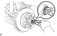
3. REMOVE FRONT DRIVE SHAFT SNAP RING (a) Using a screwdriver and hammer, remove the grease cap from the flange. (b) Using snap ring pliers, remove the snap ring. |
|
|
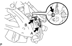
4. DISCONNECT ABS SPEED SENSOR AND WIRE HARNESS (a) Remove the 3 bolts and disconnect the ABS speed sensor and wire harness. Torque: 8.0 N·m {82 kgf·cm, 71in·lbf} for A 13 N·m {130 kgf·cm, 10ft·lbf} for B 28 N·m {290 kgf·cm, 21ft·lbf} for C |
|
|
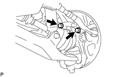
5. DISCONNECT STEERING KNUCKLE ARM (a) Remove the 2 bolts and disconnect the steering knuckle arm. Torque: 147 N·m {1,500 kgf·cm, 108ft·lbf} HINT: At the time of installation, refer to the following items.
|
|
|
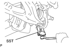
6. DISCONNECT STEERING KNUCKLE (a) Remove the cotter pin and nut. Torque: 159 N·m {1,625 kgf·cm, 117ft·lbf} HINT: At the time of installation, if the holes for the cotter pin are not aligned, tighten the nut further up to 60°. (b) Using SST, disconnect the steering knuckle from the lower suspension arm. SST: 09628-62011 |
|
7. REMOVE STEERING KNUCKLE WITH AXLE HUB
(a) Temporarily install the nut to the lower suspension arm.
(b) Support the lower suspension arm with a jack.
(c) Remove the cotter pin and nut.
Torque:
110 N·m {1,125 kgf·cm, 81ft·lbf}
HINT:
At the time of installation, if the holes for the cotter pin are not aligned, tighten the nut further up to 60°.
|
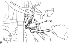
(d) Using SST, disconnect the steering knuckle from the upper suspension arm. SST: 09628-62011 |
|
(e) Remove the nut and steering knuckle with axle hub.
|
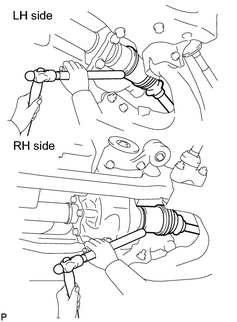
8. REMOVE FRONT DRIVE SHAFT ASSEMBLY (a) Using a brass bar and hammer, tap out the drive shaft. NOTICE: Be careful not to damage the boot, dust cover and oil seal. (b) Using a screwdriver, remove the snap ring from the inboard joint tulip. HINT: At the time of installation, refer to the following items.
|
|
|
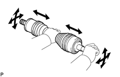
9. INSPECT FRONT DRIVE SHAFT ASSEMBLY (a) Check to see that there is no remarkable play in the outboard joint. (b) Check to see that the inboard joint slides smoothly in the thrust direction. (c) Check to see that there is no remarkable play in the radial direction of the inboard joint. (d) Check the boots for damage. |
|

|

|