| Last Modified: 7-3-2017 | 6.8:8.0.40 | Doc ID: RM0000019PS006X |
| Model Year Start: 2007 | Model: LX470 | Prod Date Range: [08/2006 - ] |
| Title: MIRROR: OUTER REAR VIEW MIRROR: REASSEMBLY; 2007 MY LX470 [08/2006 - ] | ||
REASSEMBLY
1. INSTALL OUTER MIRROR RETRACTOR LH
|
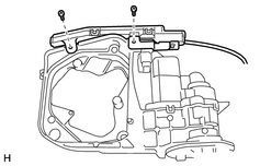
(a) Install a new tire pressure monitor antenna (1) Install the tire pressure monitor antenna with the 2 screws. |
|
(b) Install the wire harnesses
|
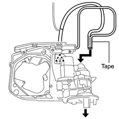
(1) Engage the clamp and insert the wire harness of the tire pressure monitor antenna and new wire harness to the hole on the upper part of the frame sub-assembly. HINT: Before inserting the 2 wire harnesses, bundle the terminals together with tape. |
|
(c) Install the mirror actuator
|
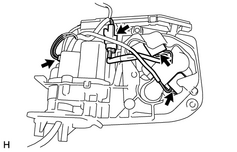
(1) Install the mirror actuator to the frame sub-assembly and connect the 4 connectors. HINT: Make sure to match the colors of the mirror actuator connectors with the colors of the makers on the mirror actuator. |
|
|
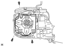
(2) Install the mirror actuator with the 3 screws. |
|
(d) Install the mirror actuator w/ frame sub-assembly
|
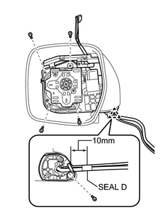
(1) Install the clamp and mirror actuator w/frame sub-assembly with 5 screws. |
|
(2) The seal d is wrapped around the harnesses at the position shown in the illustration.
distance from clamp:
10 mm (0.393 in.)
(e) Install the base
|
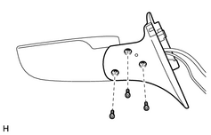
(1) Pass the wire harnesses through the base hole. |
|
(2) Using a T25 "TORX" socket wrench, install the base with 3 new screws.
Torque:
3.8 N·m {39 kgf·cm, 34in·lbf}
(f) Install the harness holder
|
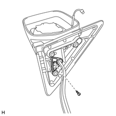
(1) Pass the wire harnesses through the harness holder and install the harness holder with the screw. |
|
(g) Install the gasket
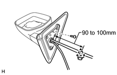
(1) Pass the wire harnesses through the gasket and install the gasket with the screw.
|
(2) Install the clamp at the position shown in the illustration. distance from gasket: 90 to 100 mm (3.54 to 3.94 in.) |
|
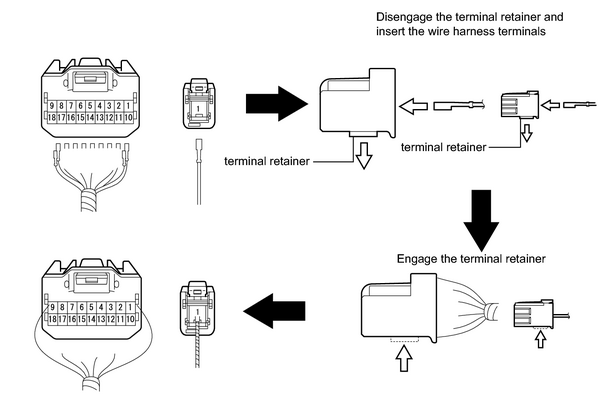
(h) Install the terminals to the connectors
(1) Based on the table, insert the wire harness terminals from the rear of the connectors.
|
1 |
2 |
3 |
4 |
5 |
6 |
7 |
8 |
9 |
10 |
11 |
12 |
13 |
14 |
15 |
16 |
17 |
18 |
|
|---|---|---|---|---|---|---|---|---|---|---|---|---|---|---|---|---|---|---|
|
LH |
- |
SB |
R - B |
B |
R |
BR |
P |
R - W |
- |
- |
V |
R - B |
L |
- |
G |
Y - B |
GR |
- |
|
RH |
- |
SB |
R - B |
B |
R |
BR |
P |
R - W |
- |
- |
V |
R - B |
L |
- |
G |
Y - B |
GR |
- |
HINT:
The R-B wire can be inserted to either terminal 3 or terminal 12 of the connector.
2. INSTALL OUTER REAR VIEW MIRROR LH
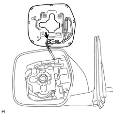
(a) Connect the connector
|
(1) Connect the connector. |
|
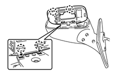
(b) Install the outer rear view mirror LH
|
(1) Engage the 4 claws and install the outer rear view mirror LH |
|

|

|