- IG1 voltage is 9.5 V or more, and condition that signals cannot be transmitted to translate ECU occurs continuously for 5 seconds or more
- IG1 voltage is 9.5 V or more, and condition that signals cannot be received from translate ECU occurs continuously for 5 seconds or more
| Last Modified: 7-3-2017 | 6.8:8.0.40 | Doc ID: RM000001A5J007X |
| Model Year Start: 2007 | Model: LX470 | Prod Date Range: [08/2006 - ] |
| Title: BRAKE CONTROL: VEHICLE STABILITY CONTROL SYSTEM: C1203/53,C1203/59; ECM Communication Circuit Malfunction; 2007 MY LX470 [08/2006 - ] | ||
|
DTC |
C1203/53 |
ECM Communication Circuit Malfunction |
|
DTC |
C1203/59 |
ECM Communication Circuit Malfunction |
DESCRIPTION
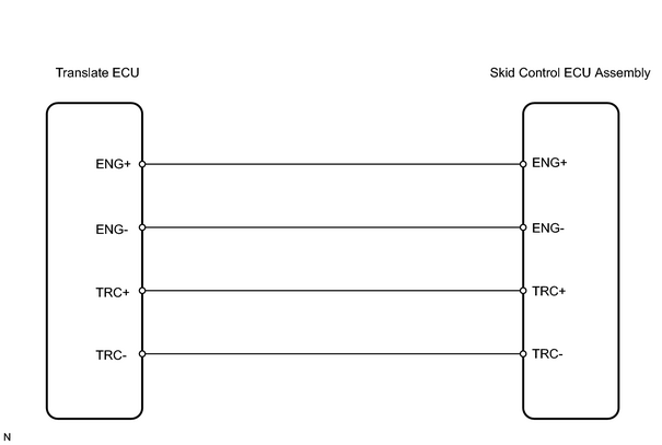
The circuit is used to send TRAC & VSC control information from the skid control ECU (TRC+, TRC-) to the translate ECU, and engine control information from the translate ECU to the skid control ECU (ENG+, ENG-).
|
DTC No. |
DTC Detection Condition |
Trouble Area |
|---|---|---|
|
C1203/53 |
Both of following conditions are met: |
|
WIRING DIAGRAM
INSPECTION PROCEDURE
PROCEDURE
|
1. |
CHECK WIRE HARNESS (SKID CONTROL ECU ASSEMBLY - TRANSLATE ECU) |
|
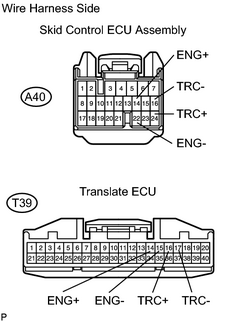
(a) Disconnect the A40 and T39 ECU connectors. (b) Measure the resistance of the wire harness side connectors. Standard resistance:
|
|
| NG |

|
|

|
2. |
CHECK ECU COMMUNICATION (SKID CONTROL ECU - TRANSLATE ECU) |
|
(a) Remove the skid control ECU. |
|
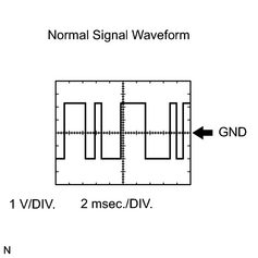
(b) Connect an oscilloscope to terminals ENG+ and ENG- or TRC+ and TRC- of skid control ECU.
(c) Start the engine, and check the signal waveform.
OK:
A waveform is output, as shown in the illustration.
| NG |
|
| OK |
|

|

|