- At a vehicle speed of 10 km/h (6 mph) or more, pulses are not input for 15 sec.
- Momentary interruption of the speed sensor signal occurs at least 7 times in the time between switching the ignition switch ON and switching it OFF.
- Continuous noise occurs in the speed sensor signals with a vehicle speed at 20 km/h (12 mph) or more.
- The condition that the speed sensor signal circuit is open continues for 0.12 sec. or more.
| Last Modified: 7-3-2017 | 6.8:8.0.40 | Doc ID: RM000001A5T007X |
| Model Year Start: 2007 | Model: LX470 | Prod Date Range: [08/2006 - ] |
| Title: BRAKE CONTROL: VEHICLE STABILITY CONTROL SYSTEM: C0200/31,C0205/32,C0210/33,C0215/34,C1235/35,C1236/36,C1238/38,C1239/39; Right Front Wheel Speed Sensor Signal Malfunction; 2007 MY LX470 [08/2006 - ] | ||
|
DTC |
C0200/31 |
Right Front Wheel Speed Sensor Signal Malfunction |
|
DTC |
C0205/32 |
Left Front Wheel Speed Sensor Signal Malfunction |
|
DTC |
C0210/33 |
Right Rear Wheel Speed Sensor Signal Malfunction |
|
DTC |
C0215/34 |
Left Rear Wheel Speed Sensor Signal Malfunction |
|
DTC |
C1235/35 |
Foreign Object is Attached on Tip of Front Speed Sensor RH |
|
DTC |
C1236/36 |
Foreign Object is Attached on Tip of Front Speed Sensor LH |
|
DTC |
C1238/38 |
Foreign Object is Attached on Tip of Rear Speed Sensor RH |
|
DTC |
C1239/39 |
Foreign Object is Attached on Tip of Rear Speed Sensor LH |
DESCRIPTION
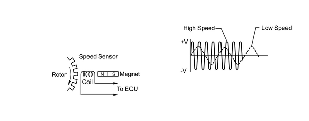
The speed sensor detects wheel speed and sends the appropriate signals to the ECU. These signals are used for control of the vehicle stability control system. The front and rear rotors each have 48 serrations.
When the rotors rotate, the magnetic field emitted by the permanent magnet in the speed sensor generates AC voltage. Since the frequency of this AC voltage changes in direct proportion to the speed of the rotor, the frequency is used by the ECU to detect the speed of each wheel.
|
DTC No. |
DTC Detection Condition |
Trouble Area |
|---|---|---|
|
C0200/31 C0205/32 C0210/33 C0215/34 |
Detection of any of the conditions 1. through 4.:
Under the above conditions, when the difference in velocity between the highest rotating and the second highest rotating wheels is within 2 km/h (1 mph), the slowest wheel rotates at 0 km/h(0 mph), and the second slowest wheel rotates at 12 km/h (7 mph) for 1 second or more. |
|
|
C1235/35 C1236/36 C1238/38 C1239/39 |
Continuous noise occurs in the speed sensor signals with a vehicle speed at 20 km/h (12 mph) or more continues for 5 sec. or more. |
|
HINT:
- DTC C0200/31 and C1235/35 are for the right front speed sensor.
- DTC C0205/32 and C1236/36 are for the left front speed sensor.
- DTC C0210/33 and C1238/38 are for the right rear speed sensor.
- DTC C0215/34 and C1239/39 are for the left rear speed sensor.
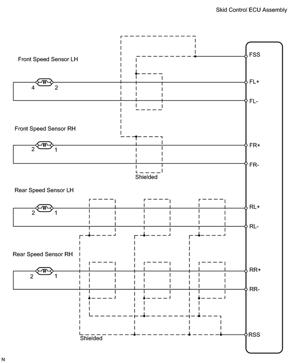
WIRING DIAGRAM
INSPECTION PROCEDURE
HINT:
When using the intelligent tester, start from *1. When not using the intelligent tester, start from *2.
PROCEDURE
|
1. |
READ DATA LIST (FRONT SPEED SENSOR)*1 |
(a) Check the DATA LIST for proper functioning of the front speed sensor.
Skid control ECU assembly
|
Item |
Measurement Item / Range (Display) |
Normal Condition |
Diagnostic Note |
|---|---|---|---|
|
WHEEL SPD FR |
Front right wheel speed / Min.: 0 km/h, Max.: 326.4 km/h |
Actual wheel speed |
Speed indicated on speedometer |
|
WHEEL SPD FL |
Front left wheel speed / Min.: 0 km/h, Max.: 326.4 km/h |
Actual wheel speed |
Speed indicated on speedometer |
|
WHEEL SPD RR |
Front right wheel speed / Min.: 0 km/h, Max.: 326.4 km/h |
Actual wheel speed |
Speed indicated on speedometer |
|
WHEEL SPD RL |
Front left wheel speed / Min.: 0 km/h, Max.: 326.4 km/h |
Actual wheel speed |
Speed indicated on speedometer |
OK:
There is almost no difference in the displayed speed value.
HINT:
There is tolerance of +- 10% in the speedometer indication.
| OK |

|
|

|
2. |
INSPECT SPEED SENSOR*2 |
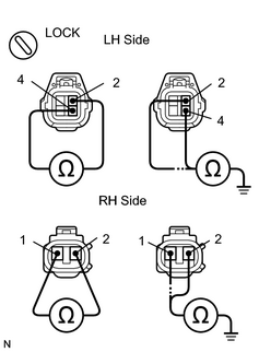
(a) Disconnect the A11 and A12 sensor connectors.
(b) Measure the resistance of the sensors.
Standard resistance:
LH
RH
|
Tester Connection |
Specified Condition |
|---|---|
|
2 (FL+) - 4 (FL-) |
0.92 to 1.22 kΩ |
|
2 (FL+) - Body ground |
10 kΩ or higher |
|
4 (FL-) - Body ground |
10 kΩ or higher |
|
Tester Connection |
Specified Condition |
|---|---|
|
1 (FR+) - 2 (FR-) |
0.92 to 1.22 kΩ |
|
1 (FR+) - Body ground |
10 kΩ or higher |
|
2 (FR-) - Body ground |
10 kΩ or higher |
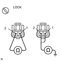
(c) Disconnect the A36 and A37 sensor connectors.
(d) Measure the resistance of the sensors.
Standard resistance:
LH
RH
|
Tester Connection |
Specified Condition |
|---|---|
|
1 (RL+) - 2 (RL-) |
1.0 to 1.4 kΩ |
|
1 (RL+) - Body ground |
10 kΩ or higher |
|
2 (RL-) - Body ground |
10 kΩ or higher |
|
Tester Connection |
Specified Condition |
|---|---|
|
1 (RR+) - 2 (RR-) |
1.0 to 1.4 kΩ |
|
1 (RR+) - Body ground |
10 kΩ or higher |
|
2 (RR-) - Body ground |
10 kΩ or higher |
HINT:
Check the speed sensor signal after the speed sensor replacement.
| NG |
|
|
|
3. |
CHECK WIRE HARNESS (SKID CONTROL ECU - SPEED SENSOR) |
| NG |
|
|
|
4. |
INSPECT SPEED SENSOR INSTALLATION |
|
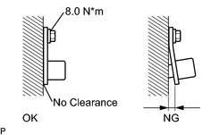
(a) Check the speed sensor installation. OK: The installation bolt is tightened properly and there is no clearance between the sensor and front steering knuckle or rear axle carrier. Torque: 8.0 N·m {82 kgf·cm, 71in·lbf} HINT: Check the speed sensor signal last. |
|
| NG |
|
|
|
5. |
INSPECT SPEED SENSOR AND SENSOR ROTOR SERRATIONS |
|
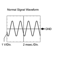
(a) Remove the skid control ECU with the connectors still connected. (b) Connect the oscilloscope to each of terminals FR+ and FR-, FL+ and FL-, RR+ and RR-, or RL+ and RL- of the skid control ECU. (c) Drive the vehicle at about 20 km/h (12 mph), and check the signal waveform. HINT:
|
|
| OK |
|
|
|
6. |
INSPECT SPEED SENSOR ROTOR AND SENSOR TIP |
Front:
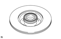
(a) Remove the front axle hub.
(b) Check the sensor rotor serrations.
OK:
No scratches, missing teeth or foreign matter.
(c) Remove the front speed sensor.
(d) Check the sensor tip.
OK:
No scratches or foreign matter on the sensor tip.
HINT:
If foreign matter (including that on the sensor rotor side) is identified, remove it and after reassembling, check the output waveform.
Rear:
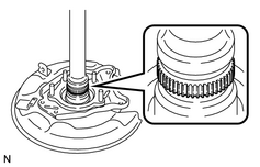
(e) Remove the rear axle shaft.
(f) Check the sensor rotor serrations.
OK:
No scratches, missing teeth or foreign matter.
(g) Remove the rear speed sensor.
(h) Check the sensor tip.
OK:
No scratches or foreign matter on the sensor tip.
HINT:
- If foreign matter (including that on the sensor rotor side) is identified, remove it and after reassembling, check the output waveform.
- Check the speed sensor signal last.
| NG |
|
| OK |
|

|

|