- The condition that ECU terminals GL1 and GL2 values are -1.5 G or less or 1.5 G or more continues for 1.2 sec. or more.
- The condition that the deceleration sensor terminal VGS voltage is 4.4 V or less or 5.6 V or more continues for 1.2 sec. or more.
- At a vehicle speed of 0 km/h (0 mph), after the difference of output value between deceleration sensor terminals GL1 and GL2 becomes 0.6 G or more, and the condition that does not become 0.4 G or less continues for 60 sec. or more.
- Deceleration sensor signal momentary open occurs 7 times or more.
| Last Modified: 7-3-2017 | 6.8:8.0.40 | Doc ID: RM000001A68005X |
| Model Year Start: 2007 | Model: LX470 | Prod Date Range: [08/2006 - ] |
| Title: BRAKE CONTROL: VEHICLE STABILITY CONTROL SYSTEM: C1244/44; Open or Short in Deceleration Sensor Circuit; 2007 MY LX470 [08/2006 - ] | ||
|
DTC |
C1244/44 |
Open or Short in Deceleration Sensor Circuit |
DESCRIPTION
This sensor detects vehicle deceleration. The sensor signal is used in ABS & BA & TRAC & VSC control. If the sensor functions abnormally, the ABS warning light comes on.
|
DTC No. |
DTC Detection Condition |
Trouble Area |
|---|---|---|
|
C1244/44 |
One of the following 1., 2., 3. or 4. is detected: |
|
WIRING DIAGRAM
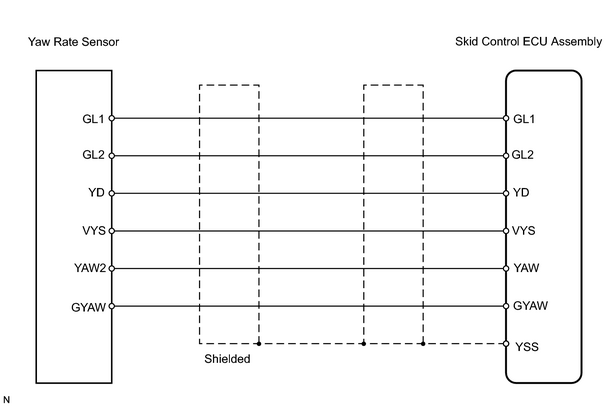
INSPECTION PROCEDURE
HINT:
When using the intelligent tester, start from *1. When not using the intelligent tester, start from *2.
PROCEDURE
|
1. |
READ VALUE USING INTELLIGENT TESTER (DECELERATION SENSOR)*1 |
(a) Check the DATA LIST for proper functioning of the deceleration sensor.
Skid control ECU assembly
|
Item |
Measurement Item / Range (Display) |
Normal Condition |
Diagnostic Note |
|---|---|---|---|
|
DECELERAT SENS |
G sensor (GL1 filter) / Min.: -1.869 G, Max.: 1.869 |
Approximately 0 +- 0.13 G when vehicle is stationary |
Reading changes when vehicle is bounced |
|
DECELERAT SENS2 |
G sensor (GL2 filter) / Min.: -1.869 G, Max.: 1.869 |
Approximately 0 +- 0.13 G when vehicle is stationary |
Reading changes when vehicle is bounced |
OK:
Deceleration value changes.
| OK |

|
|

|
2. |
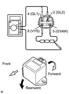
INSPECT YAW RATE SENSOR (INCLUDE DECELERATION SENSOR)*2 |
|
(a) Remove the console box and deceleration sensor. (b) Connect 3 dry cell batteries of 1.5 V in series. (c) Connect terminal 8 (VYS) to the batteries' positive (+) terminal and terminal 5 (GYAW) to the batteries' negative (-) terminal. Apply about 4.5 V between terminals 8 (VYS) and 5 (GYAW). NOTICE: Do not apply voltage of 6 V or more to terminals 8 (VYS) and 5 (GYAW). (d) Measure the voltage when the sensor is tilted forward and rearward. Standard voltage:
HINT:
|
|
| NG |
|
|
|
3. |
CHECK WIRE HARNESS (SKID CONTROL ECU ASSEMBLY - YAW RATE SENSOR) |
| NG |
|
| OK |
|

|

|