- When the condition that ECU terminal IG1 voltage is 9.5 V or more, and does not receive data from steering angle sensor continues for 1 sec. or more.
- When the steering angle sensor value changes by 360° or more with SSC signal from steering angle sensor remaining ON or OFF.
- When the condition that difference between the steering angle value at edge occurring in SSC signal and the value at edge occurring in SSC signal after turning the steering wheel one turn is out of the range from 355.5° to 364.5° occurs 10 times or more.
| Last Modified: 7-3-2017 | 6.8:8.0.40 | Doc ID: RM000001A6E007X |
| Model Year Start: 2007 | Model: LX470 | Prod Date Range: [08/2006 - ] |
| Title: BRAKE CONTROL: VEHICLE STABILITY CONTROL SYSTEM: C1231/31,C1335/35; Steering Angle Sensor Circuit Malfunction; 2007 MY LX470 [08/2006 - ] | ||
|
DTC |
C1231/31 |
Steering Angle Sensor Circuit Malfunction |
|
DTC |
C1335/35 |
Steering Angle Sensor Circuit |
DESCRIPTION
|
DTC No. |
DTC Detection Condition |
Trouble Area |
|---|---|---|
|
1231/31 |
Detection of any of the conditions 1. through 3.: |
|
|
1335/35 |
When the ECU IF1 terminal voltage is 9.5 V or more, and data transmission from the steering angle sensor is impossible for 1 sec. or more. |
|
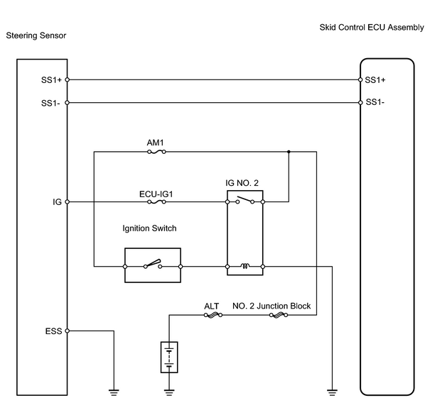
WIRING DIAGRAM
INSPECTION PROCEDURE
HINT:
When using the intelligent tester, start from *1. When not using the intelligent tester, start from *2.
PROCEDURE
|
1. |
READ DATA LIST (STEERING ANGLE SENSOR)*1 |
(a) Check the DATA LIST for proper functioning of the steering angle sensor.
Skid control ECU assembly:
|
Item |
Measurement Item / Range (Display) |
Normal Condition |
Diagnostic Note |
|---|---|---|---|
|
STEERING ANG |
Steering sensor / Min.: -1682 deg, Max.: 1877 deg |
-1682 to 1877 deg |
Turning the steering wheel changes the value Left: Becomes greater Right: Becomes smaller |
OK:
Steering wheel turning angle value must be changing.
| OK |

|
|

|
2. |
CHECK WIRE HARNESS (STEERING SENSOR - BATTERY)*2 |
|
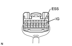
(a) Remove the column lower cover. (b) Turn the ignition switch ON. (c) Measure voltage of the wire harness side connector. Standard voltage:
|
|
| NG |
|
|
|
3. |
INSPECT STEERING ANGLE SENSOR |
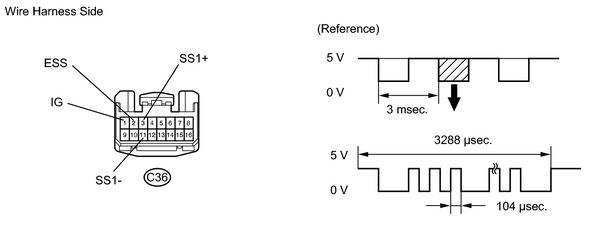
(a) Remove the No. 2 and No. 3 steering wheel lower covers, steering wheel pad, and steering wheel column upper and lower covers.
(b) Disconnect the combination switch connector (for steering angle sensor).
(c) Connect an oscilloscope to terminals 3 and 4 of the combination switch connector (for steering angle sensor).
(d) Apply battery positive voltage between terminals 1 and 2.
(e) Turn the steering wheel slowly and check the signal waveform.
OK:
A waveform is output, as shown in the illustration.
HINT:
The above signal waveform does not repeat ON and OFF regularly, and this interval changes according to the data.
| NG |
|
|
|
4. |
CHECK STEERING SENSOR DISC |
(a) Check steering sensor disc.
| NG |
|
|
|
5. |
CHECK WIRE HARNESS (STEERING SENSOR - SKID CONTROL ECU ASSEMBLY) |
| NG |
|
| OK |
|

|

|