- ECU terminal IG1 voltage is 9.5 V to 17.0 V, and the condition that yaw rate sensor voltage is out of the range from 0.25 V to 4.75 V continues for 1 sec. or more.
- The conditions that yaw rate sensor open detect circuit signal is ON and the voltage of ECU terminal IG1 is 9.5 V to 17 V continue for 1 sec. or more.
- The conditions that yaw rate sensor power source voltage is out of the range from 4.4 V to 5.6 V and the voltage of ECU terminal IF1 is 9.5 V to 17 V continue for 1 sec. or more.
- When the condition that yaw rate sensor signal is momentarily open occurs 10 times or more and the voltage of ECU terminal IG1 is 9.5 V to 17 V.
| Last Modified: 7-3-2017 | 6.8:8.0.40 | Doc ID: RM000001A6G007X |
| Model Year Start: 2007 | Model: LX470 | Prod Date Range: [08/2006 - ] |
| Title: BRAKE CONTROL: VEHICLE STABILITY CONTROL SYSTEM: C1233/33,C1234/34; Open or Short Circuit in Yaw Rate Sensor Circuit; 2007 MY LX470 [08/2006 - ] | ||
|
DTC |
C1233/33 |
Open or Short Circuit in Yaw Rate Sensor Circuit |
|
DTC |
C1234/34 |
Yaw Rate Sensor Malfunction |
DESCRIPTION
|
DTC No. |
DTC Detection Condition |
Trouble Area |
|---|---|---|
|
1233/33 |
When any of the following 1. through 4. is detected: |
|
|
C1234/34 |
Condition 1. or 2. is detected:
|
WIRING DIAGRAM
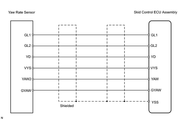
INSPECTION PROCEDURE
PROCEDURE
|
1. |
PERFORM ZERO POINT CALIBRATION OF THE YAW RATE SENSOR |
|

|
2. |
CHECK FOR DTC |
(a) Turn the ignition switch ON.
(b) Check that the VSC TRAC warning light illuminates.
(c) Check if the same DTCs are recorded.
Result
|
Result |
Proceed to |
|---|---|
|
DTC is not output (when using intelligent tester) |
A |
|
DTC is not output (when not using intelligent tester) |
B |
|
DTC is output |
C |
| B |

|
| C |
|
|
|
3. |
READ VALUE USING INTELLIGENT TESTER (YAW RATE SENSOR) |
(a) Using the DATA LIST, check for proper functioning of the yaw rate sensor.
Skid control ECU assembly:
|
Item |
Measurement Item / Range (Display) |
Normal Condition |
Diagnostic Note |
|---|---|---|---|
|
YAW RATE |
Yaw rate sensor / Min.: -128 deg/s, Max.: 128 deg/s |
- |
- |
|
YAW ZERO VALUE |
Memorized zero value / Min.: -128 deg/s, Max.: 128 deg/s |
- |
- |
OK:
Yaw rate value must be changing.
(Reference) When the yaw rate sensor is stationary output values: +-4 deg/s
| OK |
|
|
|
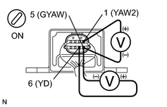
4. |
CHECK YAW RATE SENSOR (YAW2, YD VOLTAGE) |
|
(a) Remove the yaw rate sensor but do not disconnect the connector. (b) Turn the ignition switch ON. (c) Measure the voltage of the connector. Standard voltage:
|
|
| NG |
|
|
|
5. |
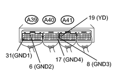
CHECK SKID CONTROL ECU ASSEMBLY (YD VOLTAGE) |
|
(a) Remove the skid control ECU but do not disconnect the connectors. (b) Turn the ignition switch ON. (c) Measure the voltage of the connectors. Standard voltage:
|
|
| NG |
|
|
|
6. |
CHECK WIRE HARNESS (SKID CONTROL ECU ASSEMBLY - YAW RATE SENSOR) |
| NG |
|
| OK |
|

|

|