- After turning the ignition switch ON, short or open circuit in pressure switch (PL) continued for more than 1 sec.
- After turning the ignition switch ON, open in pressure switch (PH) continued for more than 1 sec.
| Last Modified: 7-3-2017 | 6.8:8.0.40 | Doc ID: RM000001A6N007X |
| Model Year Start: 2007 | Model: LX470 | Prod Date Range: [08/2006 - ] |
| Title: BRAKE CONTROL: VEHICLE STABILITY CONTROL SYSTEM: C1254/54; Pressure Switch Circuit; 2007 MY LX470 [08/2006 - ] | ||
|
DTC |
C1254/54 |
Pressure Switch Circuit |
DESCRIPTION
|
DTC No. |
DTC Detection Condition |
Trouble Area |
|---|---|---|
|
C1254/54 |
Either of the following 1. or 2. is detected: |
|
WIRING DIAGRAM
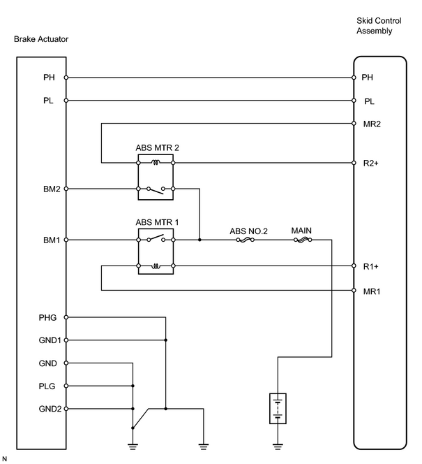
INSPECTION PROCEDURE
PROCEDURE
|
1. |
CHECK BRAKE BOOSTER PRESSURE SWITCH (PL) RESISTANCE |
|
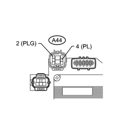
(a) Disconnect the A44 actuator connector. (b) With the ignition switch OFF, depress the brake pedal more than 40 times to decrease the accumulator pressure. HINT: When pressure in power supply system is released, reaction force becomes light. (c) Measure the resistance between terminals PL and PLG of the brake actuator. Standard resistance: 5.1 to 6.3 kΩ HINT: After inspection, connect the connector and clear the DTC. |
|
| NG |

|
|

|
2. |
CHECK BRAKE BOOSTER PRESSURE SWITCH (RH) RESISTANCE |
|
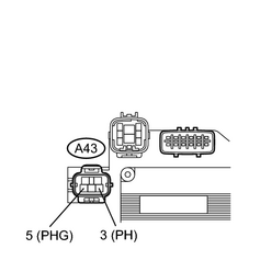
(a) Disconnect the A43 actuator connector. (b) With the ignition switch OFF, depress the brake pedal more than 40 times to decrease the accumulator pressure. HINT: When pressure in power supply system is released, reaction force becomes light. (c) Measure the resistance between terminals PH and PHG of the brake actuator. Standard resistance: 0.9 to 1.1 kΩ HINT: After inspection, connect the connector and clear the DTC. |
|
| NG |
|
|
|
3. |
CHECK WIRE HARNESS (SKID CONTROL ECU ASSEMBLY - BRAKE ACTUATOR) |
| NG |
|
| OK |
|

|

|