- After turning the ignition switch ON, open in the relay coil is detected for more than 1 sec.
- When the pressure switch does not control motor driving, the condition that the motor relay is always ON continues for more than 1 sec. due to short circuit.
- When the pressure switch (PH) detects the low pressure or while the pump motor operates to increase the pressure, the condition that the motor relay does not turn ON continues for more than 0.2 sec.
- When pressure switch does not control motor driving, the condition that the motor relay is always ON due to the welded contact continues for more than 2 sec.
| Last Modified: 7-3-2017 | 6.8:8.0.40 | Doc ID: RM000001A6P005X |
| Model Year Start: 2007 | Model: LX470 | Prod Date Range: [08/2006 - ] |
| Title: BRAKE CONTROL: VEHICLE STABILITY CONTROL SYSTEM: C1253/53; Pump Motor Relay Malfunction; 2007 MY LX470 [08/2006 - ] | ||
|
DTC |
C1253/53 |
Pump Motor Relay Malfunction |
DESCRIPTION
The ABS MTR 1 relay and ABS MTR 2 relay supply power to the hydraulic brake booster pump motor.
While the ABS & BA & TRAC & VSC are activated, the ECU switches the motor relay ON and operates the hydraulic brake booster pump motor.
|
DTC No. |
DTC Detection Condition |
Trouble Area |
|---|---|---|
|
C1253/53 |
When any of the following 1. through 4. is detected. |
|
WIRING DIAGRAM
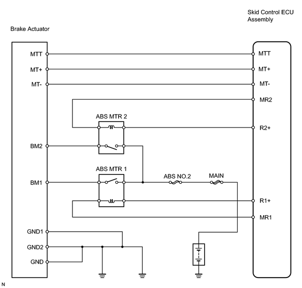
INSPECTION PROCEDURE
HINT:
When using the intelligent tester, start from *1. When not using the intelligent tester, start from *2.
PROCEDURE
|
1. |
PERFORM ACTIVE TEST USING INTELLIGENT TESTER (ABS MOTOR RELAY)*1 |
(a) Select the ACTIVE TEST, generate a control command, and then check that the ABS motor relay operates.
Skid control ECU:
|
Item |
Vehicle Condition / Test Details |
Diagnostics Note |
|---|---|---|
|
ABS MOT RELAY |
Turn ABS motor relay ON / OFF |
Operation sound of motor can be heard |
OK:
Operation sound of ABS motor is heard.
| NG |

|
|

|
2. |
CHECK WIRE HARNESS (SKID CONTROL ECU ASSEMBLY - BRAKE ACTUATOR)*2 |
| NG |
|
| OK |
|
|
3. |
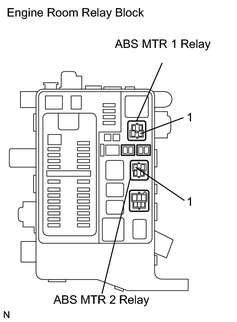
CHECK ENGINE ROOM RELAY BLOCK (ABS MTR 1 RELAY AND ABS MTR 2 RELAY)*2 |
|
(a) Remove the ABS MTR 1 relay and ABS MTR 2 relay from the engine room relay block. (b) Measure the voltage between terminal 1 of the engine room relay block (for ABS MTR 1 relay and ABS MTR 2 relay) and body ground. OK: Standard voltage 10 to 14 V |
|
| NG |
|
|
|
4. |
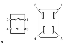
INSPECT RELAY (Marking: ABS MTR 1, ABS MTR 2) |
|
(a) Remove the ABS MTR 1 relay and ABS MTR 2 relay from the engine room relay block. (b) Measure the resistance of the relay. Standard resistance:
|
|
| NG |
|
|
|
5. |
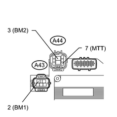
INSPECT BRAKE ACTUATOR |
|
(a) Disconnect the A43 and A44 actuator connectors. (b) Measure the resistance of the actuator. Standard resistance:
|
|
| NG |
|
|
|
6. |
CHECK WIRE HARNESS (BRAKE ACTUATOR - SKID CONTROL ECU ASSEMBLY AND ABS MTR 1 AND ABS MTR 2 RELAY) |
| NG |
|
| OK |
|

|

|