- With the vehicle running, when the pressure switch (PL) detects high pressure, although ABS, TRAC or VSC does not control, the pressure switch (PL) detects low pressure for more than 1.4 sec.
- With the vehicle running, when the pressure switch (PL) detects high pressure, although ABS, TRAC or VSC does not control, the pressure switch (PL) detects low pressure for more than 0.2 sec.
- After the ignition switch is turned ON, the pressure switch (PL) detects low pressure for more than 64 sec.
- With the vehicle running, after ignition switch has been ON, the pressure switch (PL) detects low pressure for more than 0.2 sec. although ABS, TRAC or VSC does not control and when the pressure switch is ON and stuck under high pressure.
- With the vehicle running, after ignition switch has been ON, the pressure switch (PL) detects low pressure for more than 0.2 sec. when ABS, TRAC or VSC controls, the pressure switch is ON and stuck under high pressure.
- With the vehicle running, after ignition switch is ON, the pressure switch (PL) is stuck to under low pressure although ABS, TRAC or VSC does not control for more than 1.4 sec.
- With the vehicle running, after ignition switch is ON, the pressure switch (PL) is stuck under low pressure when ABS, TRAC or VSC controls for more than 0.2 sec.
| Last Modified: 7-3-2017 | 6.8:8.0.40 | Doc ID: RM000001A6Q006X |
| Model Year Start: 2007 | Model: LX470 | Prod Date Range: [08/2006 - ] |
| Title: BRAKE CONTROL: VEHICLE STABILITY CONTROL SYSTEM: C1256/56; Accumulator Low Pressure; 2007 MY LX470 [08/2006 - ] | ||
|
DTC |
C1256/56 |
Accumulator Low Pressure |
DESCRIPTION
|
DTC No. |
DTC Detection Condition |
Trouble Area |
|---|---|---|
|
C1256/56 |
Any of the following 1. through 7. is detected. |
|
WIRING DIAGRAM
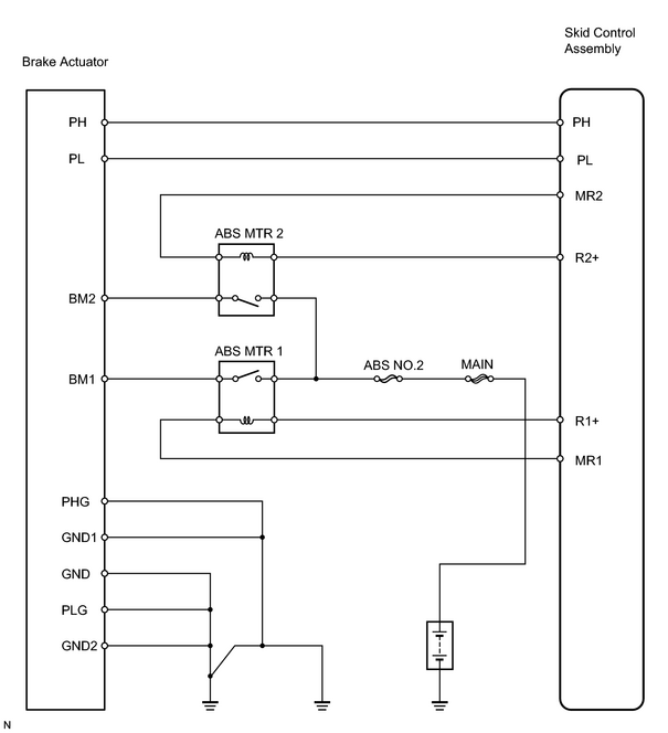
INSPECTION PROCEDURE
PROCEDURE
|
1. |
CHECK ACCUMULATOR OPERATION |
(a) Turn the ignition switch OFF, and depress the brake pedal 40 times or more.
HINT:
When pressure in power supply system is released, the brake pedal becomes easier to depress.
(b) Install the LSPV gauge (SST) to the rear brake caliper and bleed air.
SST: 09709-29018
(c) Depress the brake pedal with force of more than 343 N (35 kgf, 77 lbf) and turn the ignition switch ON. Then check the rear brake caliper pressure when an increase of pressure changes from acutely to mildly.
Standard pressure:
5,099 to 8,924 kPa (52 to 91 kgf/cm 2 , 740 to 1,294 psi) at 20°C (68°F)
HINT:
If the value is not within the standard, cool the engine room and check it again.
| NG |

|
|

|
2. |
CHECK OPERATION BRAKE ACTUATOR PUMP MOTOR |
|
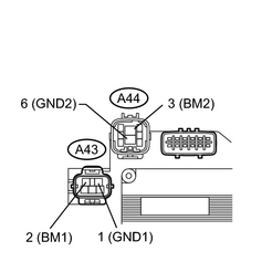
(a) Disconnect A43 and A44 actuator connectors. (b) Connect the battery positive (+) lead to terminal 2 (BM1) or 3 (BM2) and battery negative (-) lead to terminal 1 (GND1) or 6 (GND2) of the brake actuator (pump motor). OK: Operation sound of pump motor should be heard. |
|
| NG |
|
|
|
3. |
CHECK PRESSURE SWITCH (PH) OPERATION |
|
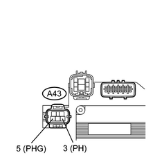
(a) Turn the ignition switch OFF, and depress the brake pedal 40 times or more. HINT: When pressure in power supply system is released, the brake pedal becomes easier to depress. (b) Install the LSPV gauge (SST) to the rear brake caliper and bleed air. SST: 09709-29018 (c) While checking the voltage between terminals 3 (PH) and 5 (PHG) of the brake actuator, depress the brake pedal with force of more than 343 N (35 kgf, 77 lbf) and turn the ignition switch ON. Then check the rear wheel cylinder pressure when the voltage changes from 6 V to 0 V. Standard pressure: 12,553 to 20,104 kPa (128 to 205 kgf/cm 2 , 1,820 to 2,916 psi) (d) Turn the ignition switch OFF and disconnect the connector A43 from the brake actuator. (e) While checking the resistance between terminals 3 (PH) and 5 (PHG), depress the brake pedal while changing the force in the range of 197 N (20 kgf, 44 lbf) to 343 N (35 kgf, 77 lbf) and check the rear wheel cylinder pressure when the resistance changes from 0 kΩ to 1 kΩ between 3 (PH) and 5 (PHG). Standard pressure: 11,964 to 18,240 kPa (122 to 186 kgf/cm 2 , 1,735 to 2,645 psi) HINT: After inspection, connect the connector, fill brake reservoir with brake fluid and clear the DTC. |
|
| OK |
|
|
|
4. |
CHECK WIRE HARNESS (SKID CONTROL ECU ASSEMBLY - BRAKE ACTUATOR) |
| NG |
|
| OK |
|
|
5. |
CHECK PRESSURE SWITCH (PL) OPERATION |
|
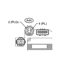
(a) Turn the ignition switch OFF, and depress the brake pedal 40 times or more. HINT: When pressure in power supply system is released, the brake pedal becomes easier to depress. (b) Install the LSPV gauge (SST) to the rear brake caliper and bleed air. SST: 09709-29018 (c) Disconnect the connector A44 from the brake actuator. (d) While checking the voltage between terminals 4 (PL) and 2 (PLG) of the brake actuator, depress the brake pedal with force of more than 343 N (35 kgf, 77 lbf) and turn the ignition switch ON. Then check the rear wheel cylinder pressure when the resistance changes from 5.7 kΩto 1.0 kΩ. Standard pressure: 9,022 to 15,102 kPa (92 to 154 kgf/cm 2 , 1,308 to 2,190 psi) (e) Turn the ignition switch OFF and disconnect the connector A44 from the brake actuator. (f) While checking the resistance between terminals 4 (PL) and 2 (PLG) of the brake actuator, depress the brake pedal while changing the force in the range of 197 N (20 kgf, 44 lbf) to 343 N (35 kgf, 77 lbf) and check the rear wheel cylinder pressure when the resistance changes from 1.0 kΩ to 5.7 kΩ. Standard pressure: 8,532 to 13,337 kPa (87 to 136 kgf/cm 2 , 1,237 to 1,934 psi) HINT: After inspection, connect the connector, fill brake reservoir with brake fluid and clear the DTC. |
|
| NG |
|
|
|
6. |
CHECK PRESSURE SWITCH (PH) AND PRESSURE SWITCH (PL) |
(a) Compare the pressure value of the rear wheel cylinder measured in check pressure switch (PL) operation with the one measured in check pressure switch (PH) operation.
OK:
Pressure when the voltage between PH and PHG becomes 0 to 6 V is greater than pressure when the resistance between PL and PLG becomes 1.0 to 5.7 kΩ
Pressure when the resistance between PH and PHG becomes 0 to 1 kΩ is greater than pressure when the resistance between PL and PLG becomes 1.0 to 5.7 kΩ
| NG |
|
| OK |
|
|
7. |
CHECK BRAKE CONTROL WIRE |
| NG |
|
|
|
8. |
CHECK BRAKE ACTUATOR PUMP MOTOR |
| NG |
|
| OK |
|

|

|