| Last Modified: 7-3-2017 | 6.8:8.0.40 | Doc ID: RM000001ABH005X |
| Model Year Start: 2007 | Model: LX470 | Prod Date Range: [08/2006 - ] |
| Title: AUDIO / VISUAL: RADIO ANTENNA POLE: ON-VEHICLE INSPECTION; 2007 MY LX470 [08/2006 - ] | ||
ON-VEHICLE INSPECTION
1. INSPECT ANTENNA MOTOR
|
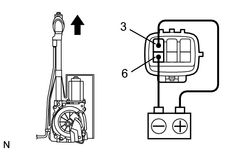
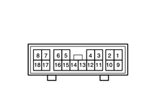
(a) Connect the positive (+) lead from the battery to terminal 3 and the negative (-) lead to terminal 6. |
|
(b) Check that the motor turns (moves upward).
NOTICE:
These tests must be done quickly (within 3-5 seconds) to prevent the coil from burning out.
|
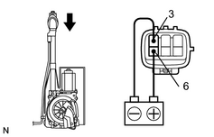
(c) Then, reverse the polarity, check that the motor turns the opposite way (moves downward). NOTICE: These tests must be done quickly (within 3-5 seconds) to prevent the coil from burning out. |
|
|
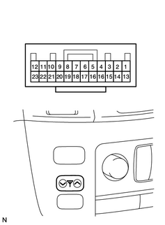
2. INSPECT ANTENNA SWITCH (w/ NAVIGATION SYSTEM) (a) Measure the voltage of the air conditioning amplifier. Standard voltage:
If the result is not as specified, the receiver may have a malfunction. |
|
|
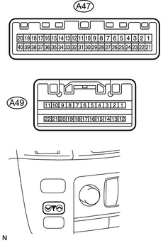
3. INSPECT ANTENNA SWITCH (w/o NAVIGATION SYSTEM) (a) Measure the voltage of the integration panel control assembly. Standard voltage:
If the result is not as specified, the receiver may have a malfunction. |
|
|
4. INSPECT ANTENNA MOTOR CONTROL RELAY (a) Disconnect the A31 relay connector. (b) Measure the resistance of the wire harness side connector. Standard resistance:
(c) Measure the voltage of the wire harness side connector. Standard voltage:
If the results are not as specified, there may be a malfunction on the wire harness side. |
|

|

|