| Last Modified: 7-3-2017 | 6.8:8.0.40 | Doc ID: RM000001ABT001X |
| Model Year Start: 2007 | Model: LX470 | Prod Date Range: [08/2006 - ] |
| Title: PARK ASSIST / MONITORING: NIGHT VIEW SYSTEM: Entire Image is Dark, has Halos, or has Ghosting; 2007 MY LX470 [08/2006 - ] | ||
|
Entire Image is Dark, has Halos, or has Ghosting |
DESCRIPTION
Dark screen, blurred image, and double image occur by dirt on the windshield glass and misadjustment of the rheostat of the night view switch by the user.
WIRING DIAGRAM
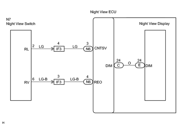
INSPECTION PROCEDURE
PROCEDURE
|
1. |
CHECK INSTALLATION OF FRONT BUMPER |
(a) Check installation of the front bumper.
HINT:
The night view projector is installed in the front bumper.
The light axis of the night view projector should be normal if the front bumper is installed on the body properly.
OK:
No damage or deformation of the front bumper and the night view projector.
All repairs should be completed based on the standard value in the body repair manual.
HINT:
If objects are displayed too bright on the screen when the objects stand or exist within 100 m (328 ft.), the light axis of the night projector may not be at the correct angle.
| NG |

|
|

|
2. |
CHECK WINDSHIELD GLASS IN FRONT OF NIGHT VIEW CAMERA |
(a) Check the windshield glass in front of the night view camera.
OK:
Windshield glass is clean.
HINT:
Night view camera cleaning method
![2007 MY LX470 [08/2006 - ]; WINDSHIELD / WINDOWGLASS: WINDSHIELD GLASS: ADJUSTMENT+](../../../../stylegraphics/info.gif "2007 MY LX470 [08/2006 - ]; WINDSHIELD / WINDOWGLASS: WINDSHIELD GLASS: ADJUSTMENT+") .
.
| NG |
|
|
|
3. |
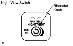
CHECK NIGHT VIEW RHEOSTAT OPERATION |
|
(a) Adjust the rheostat and check if the display returns to normal. OK: Display is normal after adjusting rheostat. |
|
| OK |
|
|
|
4. |
CHECK NIGHT VIEW SWITCH OPERATION |
|
(a) Check if the display illumination brightness can be changed (rheostat function). OK: Illumination brightness can be slightly changed (though not significantly). (NG: No change in brightness.) |
|
| NG |
|
|
|
5. |
INSPECT NIGHT VIEW SWITCH |
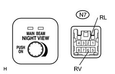
(a) Remove the night view switch.
(b) Disconnect the connector from the night view switch.
|
(c) Measure the resistance between terminals RL and RV of the night view switch. Standard resistance:
|
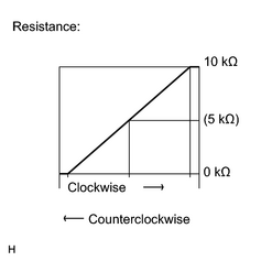
|
| NG |
|
|
|
6. |
CHECK NIGHT VIEW CAMERA |
(a) Remove the over head junction (map light cover).
(b) Disconnect the connector from the night view camera.
(c) Connect SST to the wire harness of the night view camera on the body side as shown in the illustration.
SST: 09991-00610
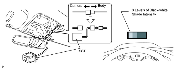
(d) Turn the ignition switch ON.
(e)
Switch to inspection mode
.
(f) Check the screen of the night view display.
OK:
3 levels of black-white shade intensity displayed.
| NG |
|
| OK |
|
|
7. |
CHECK NIGHT VIEW ECU (REO VOLTAGE) |
(a) Remove the combination meter assembly.
(b) Turn the ignition switch ON.
(c)
Switch to inspection mode
.
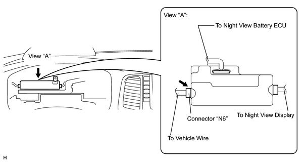
|
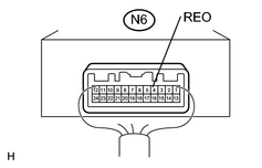
(d) Measure the voltage between terminal REO of the night view ECU connector "N6" and body ground while rotating rheostat.
(Terminals of ECU:
Standard voltage: The voltage charges within 0 to 5 V when rotating the rheostat. |
|
| NG |
|
|
|
8. |
CHECK NIGHT VIEW ECU (DIM VOLTAGE) |
(a) Turn the ignition switch ON.
(b)
Switch to inspection mode
.
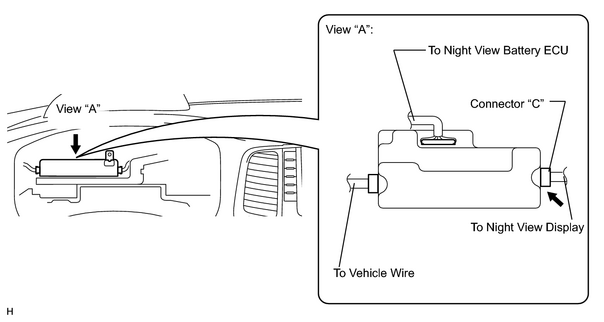
|
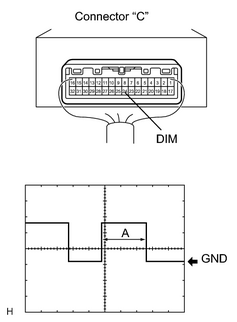
(c) Using an oscilloscope, check the output waveform between terminal DIM of the night view ECU connector "C" and body ground.
(Terminals of ECU:
OK: The duty ratio changes (length of "A" becomes shorter) while rotating the night view switch clockwise. (Reference) oscilloscope connection
|
|
| NG |
|
|
|
9. |
CHECK USING INSPECTION MODE |
(a)
Switch to inspection mode
.
(b) Verify that the screen is normal by operating the night view switch (rheostat function).
OK:
Normal screen is displayed.
| NG |
|
| OK |
|
|
10. |
INSPECT NIGHT VIEW SWITCH |
(a) Remove the night switch.
(b) Disconnect the connector from the night view switch.
|
(c) Measure the resistance between terminals RL and RV of the night view switch. Standard resistance:
|
|
| NG |
|
| OK |
|

|

|