| Last Modified: 7-3-2017 | 6.8:8.0.40 | Doc ID: RM000001ABU001X |
| Model Year Start: 2007 | Model: LX470 | Prod Date Range: [08/2006 - ] |
| Title: PARK ASSIST / MONITORING: NIGHT VIEW SYSTEM: Night View Projector does not Turn on; 2007 MY LX470 [08/2006 - ] | ||
|
Night View Projector does not Turn on |
DESCRIPTION
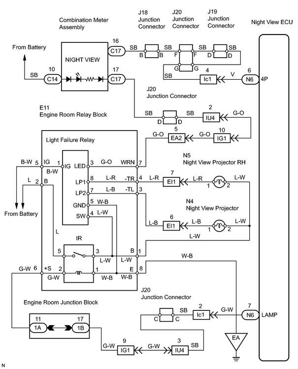
The night view projector does not come on when the bulb has a short circuit, the night view relay malfunctions or the signals to operate the system are not input to the night view ECU.
HINT:
If one of the bulbs does not come on, it may be burned out.
The light failure relay turns the night view warning light in the combination meter on whenever one of the night view projectors has a burned out bulb.
WIRING DIAGRAM
INSPECTION PROCEDURE
PROCEDURE
|
1. |
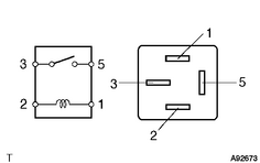
INSPECT RELAY (Marking: IR) |
|
(a) Remove the IR relay from the engine room relay block. (b) Measure the resistance of the relay. Standard resistance:
|
|
| NG |

|
|

|
2. |
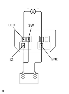
CHECK LIGHT FAILURE RELAY |
|
(a) Remove the light failure relay from engine room relay block. (b) Connect the battery positive (+) terminal to terminal IG and terminal SW and the battery negative (-) terminal to terminal GND. (c) Measure the resistance of the light failure relay terminal between LED and GND. Standard resistance: Below 1 Ω within 1.5 seconds of the connection. |
|
| NG |
|
|
|
3. |
CHECK NIGHT VIEW WARNING LIGHT (LED BULB) |
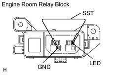
(a) Remove the light failure relay from the engine room relay block.
(b) Turn the ignition switch ON.
(c)
Switch to inspection mode
![2007 MY LX470 [08/2006 - ]; PARK ASSIST / MONITORING: NIGHT VIEW SYSTEM: OPERATION CHECK](../../../../stylegraphics/info.gif "2007 MY LX470 [08/2006 - ]; PARK ASSIST / MONITORING: NIGHT VIEW SYSTEM: OPERATION CHECK") .
.
(d) Using SST (diagnosis check wire), connect terminals LED and GND of the engine room relay block.
SST: 09843-18040
|
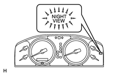
(e) Check that the night view warning light in the combination meter assembly comes on. OK: The night view warning light comes on. |
|
| NG |
|
|
|
4. |
CHECK WIRE HARNESS (COMBINATION METER ASSEMBLY - LIGHT FAILURE RELAY) |
(a) Remove the combination meter assembly.
(b) Disconnect the connector "C17" from the combination meter assembly.
HINT:
Remove the light failure relay from engine room relay block.
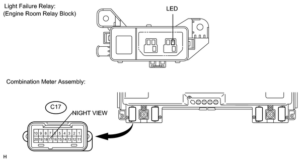
(c) Measure the resistance between terminal WRN and body ground.
Standard resistance:
10 kΩ or higher
(d) Check the resistance between terminal WRN and NIGHT VIEW.
Standard resistance:
Below 1 Ω
| NG |
|
| OK |
|
|
5. |
CHECK USING INSPECTION MODE |
(a) Turn the ignition switch ON.
(b)
Switch to inspection mode
(c) Check that the night view projector turns on in inspection mode.
OK:
The night view projector turns on.
| OK |
|
|
|
6. |
CHECK NIGHT VIEW ECU (LAMP VOLTAGE) |
HINT:
Remove the night view relay from the engine room relay block.
(a) Remove the combination meter assembly.
(b) Turn the ignition switch ON.
(c)
Switch to inspection mode
.
|
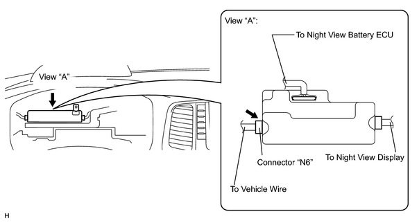
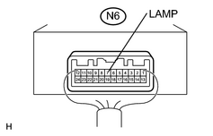
(d) Measure the voltage between terminal LAMP of the night view ECU connector "N6" and body ground.
(Terminals of ECU:
Standard voltage: Above 10 V |
|
| NG |
|
| OK |
|
REPAIR OR REPLACE HARNESS AND CONNECTOR (NIGHT VIEW ECU - ENGINE ROOM RELAY BLOCK (IR RELAY)) |
|
7. |
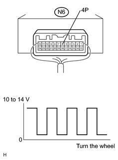
CHECK NIGHT VIEW ECU (4P VOLTAGE) |
(a) Remove the combination meter assembly.
(b) Jack up either of the front and rear wheels.
(c) Shift the shift lever to neutral.
(d) Attach a test lead to terminal 4P of the night view ECU.
(e) Reconnect the combination meter assembly connectors.
(f) Turn the ignition switch ON.
|
(g) Measure the voltage between terminal 4P of the night view ECU connector "N6" and body ground while turning the wheel slowly.
(Terminals of ECU:
Standard voltage: The pulse generation is as shown in the illustration. |
|
| NG |
|
| OK |
|

|

|