| Last Modified: 7-3-2017 | 6.8:8.0.40 | Doc ID: RM000001ADD005X |
| Model Year Start: 2007 | Model: LX470 | Prod Date Range: [08/2006 - ] |
| Title: DIFFERENTIAL: FRONT DIFFERENTIAL CARRIER ASSEMBLY: DISASSEMBLY; 2007 MY LX470 [08/2006 - ] | ||
DISASSEMBLY
1. REMOVE FRONT DIFFERENTIAL CARRIER COVER
(a) Remove the 9 bolts and nut from the carrier cover.
(b) Using a brass bar and hammer, separate the cover from the carrier.
(c) Remove the breather plug from the differential carrier cover.
(d) Remove the 2 bolts and oil deflector from the differential carrier cover.
|
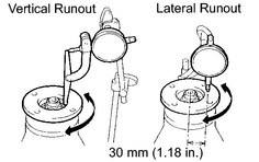
2. INSPECT FRONT DRIVE PINION COMPANION FLANGE SUB-ASSEMBLY (a) Using a dial indicator, measure the vertical runout of the companion flange. Maximum runout: 0.14 mm (0.0055 in.)
|
|
|
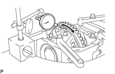
3. INSPECT RING GEAR RUNOUT (a) Using a dial indicator, measure the ring gear runout. Maximum runout: 0.07 mm (0.0028 in.)
|
|
|
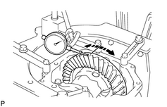
4. INSPECT RING GEAR BACKLASH (a) Using a dial indicator, while holding the drive pinion flange measure the ring gear backlash. Standard backlash: 0.13 to 0.18 mm (0.0051 to 0.0071 in.) HINT: Measure at 3 or more places on the circumference of the ring gear.
|
|
|
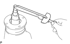
5. INSPECT DRIVE PINION PRELOAD (a) Using a torque wrench, measure the drive pinion preload using the backlash of the drive pinion and ring gear. Torque: Standard preload (at start of torque) - 0.6 to 0.9 N·m {6 to 9 kgf·cm, 4.3 to 6.9in·lbf} |
|
6. INSPECT TOTAL PRELOAD
(a) Using a torque wrench, measure the total preload.
Torque:
Standard total preload (at start of torque) -
0.4 to 0.6 N·m {4 to 6 kgf·cm, 3.5 to 5.2in·lbf} + drive pinion preload
- If necessary, disassemble and inspect the differential.
7.
INSPECT TOOTH CONTACT BETWEEN RING GEAR AND DRIVE PINION
![2007 MY LX470 [08/2006 - ]; DIFFERENTIAL: FRONT DIFFERENTIAL CARRIER ASSEMBLY: REASSEMBLY+](../../../../stylegraphics/info.gif "2007 MY LX470 [08/2006 - ]; DIFFERENTIAL: FRONT DIFFERENTIAL CARRIER ASSEMBLY: REASSEMBLY+")
|
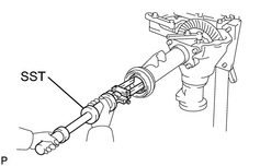
8. REMOVE SIDE GEAR SHAFT OIL SEAL (a) Using SST, remove the 2 side gear shaft oil seals. SST: 09308-00010 |
|
|
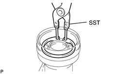
9. REMOVE FRONT DIFFERENTIAL TUBE ASSEMBLY (a) Using SST, remove the snap ring. SST: 09350-30020 09350-07060 (b) Using a snap ring expander, remove the snap ring. (c) Remove the 4 bolts and differential tube with side gear shaft from the differential carrier. (d) Remove the side gear shaft from the differential tube. |
|
|
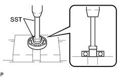
10. REMOVE DIFFERENTIAL SIDE GEAR SHAFT BEARING (a) Using SST and a press, remove the bearing from side gear shaft. SST: 09950-60010 09951-00410 SST: 09950-70010 09951-07100 |
|
11. REMOVE FRONT DRIVE PINION COMPANION FLANGE SUB-ASSEMBLY
(a) Using a chisel and hammer, unstake the nut.
|
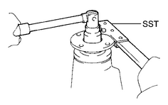
(b) Using SST to hold the flange, remove the nut. SST: 09330-00021 |
|
|
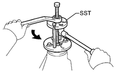
(c) Using SST, remove the companion flange. SST: 09950-30012 09951-03010 09953-03010 09954-03010 09955-03030 09956-03020 |
|
|
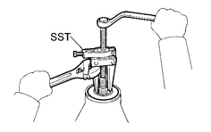
12. REMOVE FRONT DIFFERENTIAL CARRIER OIL SEAL (a) Using SST, remove the oil seal from the differential carrier. SST: 09308-10010 |
|
13. REMOVE FRONT DIFFERENTIAL DRIVE PINION OIL SLINGER
(a) Remove the oil slinger.
|
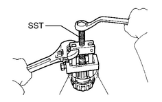
14. REMOVE FRONT DRIVE PINION REAR TAPERED ROLLER BEARING (a) Using SST, remove the rear bearing from the drive pinion. SST: 09556-22010
|
|
15. REMOVE FRONT DIFFERENTIAL CASE SUB-ASSEMBLY
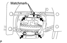
(a) Place matchmarks on the bearing cap and differential carrier.
(b) Remove the 4 bolts and 2 bearing caps.
|
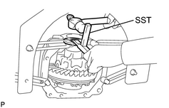
(c) Using SST and a hammer, remove the 2 side bearing plate washers. SST: 09504-22011 HINT: Measure the plate washer and note the thickness. |
|
(d) Remove the differential case with the bearing outer races from the differential carrier.
HINT:
Tag the bearing outer races to show the location for reassembling.
16. REMOVE DRIVE PINION SUB-ASSEMBLY
17. REMOVE FRONT DIFFERENTIAL DRIVE PINION BEARING SPACER
|
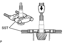
18. REMOVE FRONT DRIVE PINION FRONT TAPERED ROLLER BEARING (a) Using SST and a press, remove the front bearing from the drive pinion. SST: 09950-00020 HINT: If the drive pinion or ring gear is damaged, replace them as a set. (b) Remove the washer. |
|
19. REMOVE REAR BEARING OUTER RACE
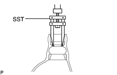
(a) Using SST, remove the rear bearing outer race.
SST: 09308-00010
|
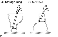
(b) Using a brass bar and hammer, remove the oil storage ring and front bearing outer race. |
|
|
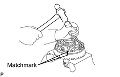
20. REMOVE DIFFERENTIAL RING GEAR (a) Place matchmarks on the ring gear and differential case. (b) Using a screwdriver and hammer, unstake the 5 lock plates. (c) Remove the 10 bolts and 5 lock plates. (d) Using a plastic-faced hammer, tap on the ring gear to separate it from the differential case. |
|
21. INSPECT DIFFERENTIAL CASE
(a) Place the bearing outer races on their respective bearings. Check that the left and right outer races are not interchanged.
(b) Install the assembled plate washers onto the side bearing.
(c) Install the differential case in the differential carrier.
HINT:
If it is difficult to install the differential case into the carrier, replace the plate washer with a thinner one.
- However, select a plate washer that allows no clearance between it and the carrier.
(d) Align matchmarks on the bearing cap and differential carrier.
(e) Install and uniformly tighten the 4 bolts a little at a time.
|
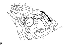
(f) Using a dial indicator, measure the differential case runout. Maximum runout: 0.07 mm (0.0028 in.)
|
|
(g) Remove the differential case.
|
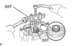
22. REMOVE FRONT DIFFERENTIAL CASE BEARING (a) Using SST, remove the 2 side bearings from the differential case. SST: 09950-40011 09951-04020 09952-04010 09953-04030 09954-04010 09955-04061 09957-04010 09958-04011 SST: 09950-60010 09951-00480 HINT: Fix the claws of SST to the notches in the differential case. |
|
|
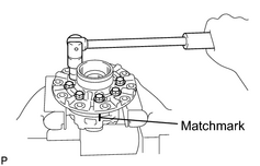
23. DISASSEMBLE DIFFERENTIAL CASE (a) Place matchmarks on the LH and RH case. (b) Remove the 8 bolts uniformly, a little at a time. (c) Using a plastic-faced hammer, separate the LH and RH cases. (d) Remove the spider, 2 side gears, side gear thrust washers, 4 pinion gears and pinion gear thrust washers from the RH differential case. |
|

|

|