| Last Modified: 7-3-2017 | 6.8:8.0.40 | Doc ID: RM000001AI2003X |
| Model Year Start: 2007 | Model: LX470 | Prod Date Range: [08/2006 - ] |
| Title: NAVIGATION: NAVIGATION SYSTEM: AVC-LAN Circuit; 2007 MY LX470 [08/2006 - ] | ||
|
AVC-LAN Circuit |
DESCRIPTION
Each unit of navigation system connected with AVC-LAN (communication bus) transfers the signal of each switch.
When +B short and GND short occur in the AVC-LAN, the navigation system will not function normally as the communication is discontinued.
In the AVC-LAN, the multi-display becomes the master of the communication, and the radio receiver assembly has a terminator necessary for transmitting the communication.
The multi-display is connected between the navigation ECU and radio receiver assembly. The navigation system has a structure that makes communication impossible without the navigation ECU, multi-display or radio receiver assembly.
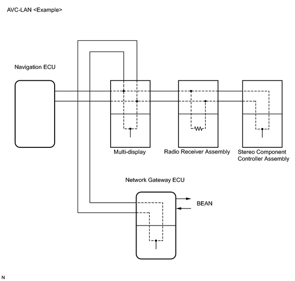
WIRING DIAGRAM
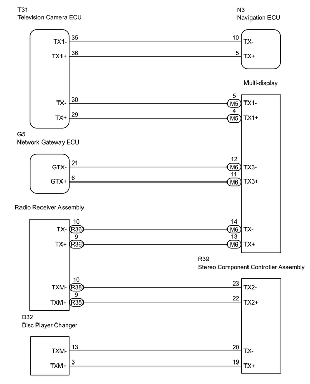
INSPECTION PROCEDURE
PROCEDURE
|
1. |
REPLACE STEREO COMPONENT CONTROLLER ASSEMBLY |
(a) Replace the stereo component controller assembly with a normal panel.
(b) Check that the display changes by pressing either of the Panel or Touch switches on the display.
HINT:
It can be determined that the AVC-LAN has recovered if the display is changed.
| OK |

|
|

|
2. |
CHECK WIRE HARNESS (RADIO RECEIVER - STEREO COMPONENT CONTROLLER) |
| NG |
|
|
|
3. |
REPLACE NAVIGATION ECU |
(a) Replace the navigation ECU with a normal ECU.
(b) Check that the display changes by pressing either of the Panel or Touch switches on the display.
HINT:
It can be determined that the AVC-LAN has recovered if the display is changed.
| OK |
|
|
|
4. |
CHECK WIRE HARNESS (NAVIGATION ECU - MULTI-DISPLAY) |
| NG |
|
|
|
5. |
REPLACE NETWORK GATEWAY ECU |
(a) Replace the gateway ECU with a normal ECU.
(b) Check that the display changes by pressing either of the Panel or Touch switches on the display.
HINT:
It can be determined that the AVC-LAN has recovered if the display is changed.
| OK |
|
|
|
6. |
CHECK WIRE HARNESS (MULTI-DISPLAY - NETWORK GATEWAY ECU) |
| NG |
|
|
|
7. |
SKIP MULTI-DISPLAY AND CHECK AVC-LAN |
(a) Disconnect the M5 and M6 display connectors.
(b) Using SSTs (Diagnosis check wire P/N 09893-12040), connect the terminal TX1+ of connector "M5" and TX+ of connector "M6", the terminal TX1- of connector "M5" and TX- of connector "M6" respectively of the multi-display.
(c) Operate radio receiver assembly (CD, Cassette tape, etc.) and check that sound comes out from the speaker. (Check that AVC-LAN is recovered.)
| OK |
|
|
|
8. |
SKIP TELEVISION CAMERA ECU AND CHECK AVC-LAN |
(a) Disconnect the T21 ECU connector.
(b) Using SSTs (Diagnosis check wire P/N 09893-12040), connect the terminal TX1+ and TX+ of connector "T21", the terminal TX- of connector and TX1- of connector "T21" respectively of the multi-display.
(c) Operate the radio receiver assembly (CD, Cassette tape, etc.) and check that sound comes out from the speaker. (Check that AVC-LAN is recovered.)
| OK |
|
|
|
9. |
SKIP RADIO RECEIVER ASSEMBLY AND CHECK AVC-LAN |
(a) Disconnect the R38 receiver connector.
(b) Using SST (Navigation Check Wire P/N 09843-18050), connect the terminal TX+ to terminal TX- of "R38" connector of the radio receiver assembly.
(c) Operate the panel switch and the touch switch of the multi-display and check that the navigation functions. (Check that AVC-LAN is recovered.)
| OK |
|
| NG |
|

|

|