| Last Modified: 7-3-2017 | 6.8:8.0.40 | Doc ID: RM000001ATW004X |
| Model Year Start: 2007 | Model: LX470 | Prod Date Range: [08/2006 - ] |
| Title: INSTRUMENT PANEL: INSTRUMENT PANEL SAFETY PAD: REMOVAL; 2007 MY LX470 [08/2006 - ] | ||
REMOVAL
1. SHIP MODE SETTING (w/ CD Changer Built in Audio System)
(a) Take out all CDs.
NOTICE:
If they cannot be taken out, do not attempt to take them out forcibly. Send the unit for repair.
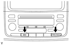
(b) Turn the ignition switch to ACC while pressing the "SEEK UP" and "DISC" switches at the same time.
HINT:
When the ship mode is set, "SHIP" must be displayed.
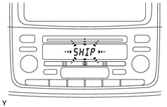
(c) Turn the ignition switch to OFF, and disconnect the negative battery cable.
NOTICE:
Connecting the negative battery cable automatically finishes the ship mode.
2. DISCONNECT CABLE FROM NEGATIVE BATTERY TERMINAL
CAUTION:
Wait at least 90 seconds after disconnecting the cable from the negative (-) battery terminal to prevent airbag and seat belt pretensioner activation.
|
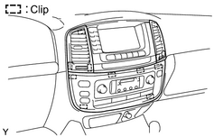
3. REMOVE INSTRUMENT CLUSTER FINISH PANEL CENTER (a) Using a moulding remover, detach the 6 clips and remove the finish panel. (b) Disconnect the connector. |
|
4. REMOVE NO. 3 INSTRUMENT PANEL REGISTER ASSEMBLY
(a) Using a moulding remover, detach the 3 clips and remove the register.
5. REMOVE NO. 2 INSTRUMENT PANEL REGISTER ASSEMBLY
(a) Using a moulding remover, detach the 3 clips and remove the register.
|
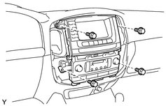
6. REMOVE RADIO WITH AIR CONDITIONING CONTROL ASSEMBLY (a) Remove the 4 bolts. (b) Disconnect the radio with air conditioning control assembly cable, and remove the radio with air conditioning control assembly and the connector. |
|
|
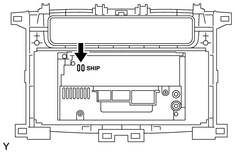
7. SHIP MODE CONFIRMATION (w/ CD Changer Built in Audio System) (a) Check that metal can be seen from the hole marked "SHIP" on the back of the radio with air conditioning control assembly. NOTICE: If the metal part cannot be seen from the hole on the back of the air conditioner control assembly, repeat "SHIP MODE". |
|
8. REMOVE FRONT DOOR SCUFF PLATE RH
9. REMOVE FRONT DOOR SCUFF PLATE LH
10. REMOVE COWL SIDE TRIM BOARD RH
11. REMOVE COWL SIDE TRIM BOARD LH
12. REMOVE FRONT DOOR OPENING TRIM WEATHERSTRIP RH
13. REMOVE FRONT DOOR OPENING TRIM WEATHERSTRIP LH
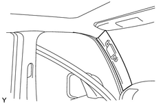
14. REMOVE FRONT PILLAR GARNISH RH
(a) Using a screwdriver, remove the 2 assist grip plugs, then remove the 2 screws and the assist grip.
HINT:
Tape the screwdriver tip before use.
|
(b) Using a screwdriver, remove the garnish. HINT: Tape the screwdriver tip before use. |
|
15. REMOVE FRONT PILLAR GARNISH LH
HINT:
Use the same procedures described for the RH side.
16.
REMOVE STEERING PAD ASSEMBLY
![2007 MY LX470 [08/2006 - ]; SUPPLEMENTAL RESTRAINT SYSTEM: STEERING PAD: REMOVAL+](../../../../stylegraphics/info.gif "2007 MY LX470 [08/2006 - ]; SUPPLEMENTAL RESTRAINT SYSTEM: STEERING PAD: REMOVAL+")
17.
REMOVE STEERING WHEEL ASSEMBLY
|
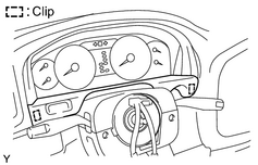
18. REMOVE INSTRUMENT CLUSTER FINISH PANEL SUB-ASSEMBLY (a) Using a screwdriver, detach the 2 clips and remove the finish panel, and then disconnect the connectors. HINT: Tape the screwdriver tip before use. |
|
19. REMOVE HOOD LOCK CONTROL LEVER SUB-ASSEMBLY
(a) Remove the 2 screws and control cable.
20. REMOVE FUEL LID OPEN LEVER SUB-ASSEMBLY
(a) Remove the 2 screws and control cable lever.
|
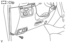
21. REMOVE NO. 1 LOWER PANEL (a) Remove the screw. (b) Using a screwdriver, detach the 5 clips and remove the No. 1 lower panel, and then disconnect the connectors. HINT: Tape the screwdriver tip before use. |
|
22. REMOVE LH LOWER PANEL
(a) Remove the 3 bolts and the LH lower panel.
23. REMOVE STEERING COLUMN COVER
(a) Remove the 3 screws and column cover.
|
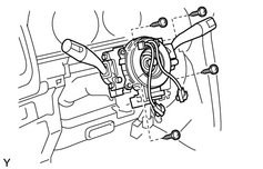
24. REMOVE COMBINATION SWITCH ASSEMBLY (a) Disconnect the connectors. (b) Remove the clamp. (c) Remove the 4 screws and combination switch. |
|
|
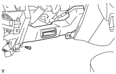
25. REMOVE NO. 2 HEATER TO REGISTER DUCT (a) Disconnect the connector, and remove the screw and the No. 1 transceiver finish plate assembly. (b) Remove the screw and the No. 2 heater to register duct. |
|
|
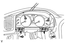
26. REMOVE COMBINATION METER (a) Disconnect the connectors. HINT: The connectors can be disconnected by loosening the bolts. (b) Remove the 4 screws. (c) Using a screwdriver, remove the combination meter. HINT: Tape the screwdriver tip before use. |
|
|
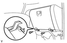
27. REMOVE GLOVE COMPARTMENT DOOR SUB-ASSEMBLY (a) Remove the 2 screws. (b) Remove the glove compartment door, then disconnect the glove compartment door damper clip. |
|
|
28. DISCONNECT AIRBAG CONNECTOR (a) Using a screwdriver, remove the No. 1 under cover. HINT: Tape the screwdriver tip before use. (b) Slide the airbag connector to pull it out from the No. 1 under cover. (c) Disconnect the airbag connector. NOTICE: When handling the airbag connector, take care not to damage the airbag wire harness. |
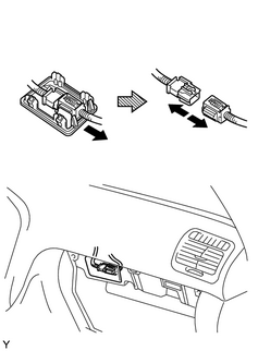
|
29. REMOVE INSTRUMENT PANEL FINISH PANEL LH LOWER
(a) Remove the 3 screws and the finish panel.
|
30. REMOVE UPPER CONSOLE PANEL SUB-ASSEMBLY (a) Remove the transfer shift lever knob. (b) Using a screwdriver, detach the 6 clips and remove the upper console panel. HINT: Tape the screwdriver tip before use. |
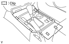
|
|
31. REMOVE REAR CONSOLE END PANEL SUB-ASSEMBLY (a) Remove the rear console cup holder box. (b) Remove the 2 screws. (c) Using a screwdriver, detach the 2 clips and remove the end panel. HINT: Tape the screwdriver tip before use. |
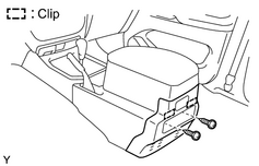
|
32. REMOVE REAR RADIO CONTROL PANEL
(a) Disconnect the connector.
(b) Remove the 3 screws and the control panel.
|
33. REMOVE REAR CONSOLE BOX SUB-ASSEMBLY (w/o Disc Player Changer, w/o LEXUS Link System) (a) Remove the 4 bolts, 4 screws and console box. |
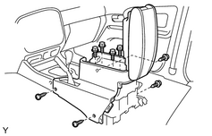
|
|
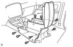
34. REMOVE REAR CONSOLE BOX SUB-ASSEMBLY (w/ Disc Player Changer) (a) Remove the 2 bolts, 6 screws and console box. |
|
|
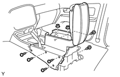
35. REMOVE REAR CONSOLE BOX SUB-ASSEMBLY (w/ LEXUS Link System) (a) Remove the 2 nuts, 6 screws and console box. |
|
|
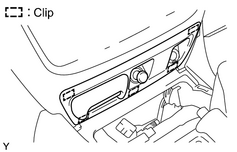
36. REMOVE INSTRUMENT CLUSTER FINISH PANEL CENTER LOWER (a) Using a screwdriver, detach the 5 clips and remove the cluster finish panel, and then disconnect the connectors. HINT: Tape the screwdriver tip before use. |
|
37. REMOVE FRONT ASH RECEPTACLE RETAINER
(a) Remove the ash receptacle box.
(b) Remove the 2 screws and ash receptacle retainer.
|
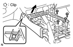
38. REMOVE FRONT CONSOLE BOX (a) Remove the 4 bolts, console box and No. 4 console box mounting bracket. |
|
|
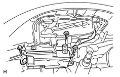
39. REMOVE NIGHT VIEW CONTROL ECU (w/ Night View System) (a) Remove the 3 bolts. (b) Disconnect the connectors. (c) Remove the ECU. |
|
|
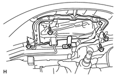
40. REMOVE NIGHT VIEW DISPLAY (w/ Night View System) (a) Remove the 4 screws. (b) Remove the display. |
|
41. REMOVE INSTRUMENT PANEL SAFETY PAD SUB-ASSEMBLY
(a) Disconnect the junction connectors.
HINT:
The connectors can be disconnected by loosening the bolts.
|
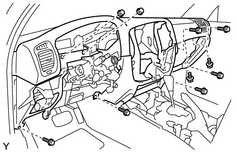
(b) Disconnect the connectors, then remove the 8 bolts, 2 nuts and instrument panel. |
|
(c) Remove the screw and No. 2 transceiver finish plate assembly.
42. REMOVE ECM
43. REMOVE NO. 3 HEATER TO REGISTER DUCT
44. REMOVE NO. 4 HEATER TO REGISTER DUCT
45. REMOVE GLOVE COMPARTMENT DOOR DAMPER
46. REMOVE INSTRUMENT PANEL TO FLOOR BRACE SUB-ASSEMBLY
47. REMOVE NO. 1 INSTRUMENT PANEL BRACE SUB-ASSEMBLY
48. REMOVE NO. 2 NIGHT VIEW ECU (w/ Night View System)
(a) Remove the 2 screws and the ECU.
49. REMOVE INSTRUMENT PANEL REINFORCEMENT ASSEMBLY

|

|