| Last Modified: 7-3-2017 | 6.8:8.0.40 | Doc ID: RM000001B6X005X |
| Model Year Start: 2007 | Model: LX470 | Prod Date Range: [08/2006 - ] |
| Title: WIPER AND WASHER: WIPER SWITCH: INSPECTION; 2007 MY LX470 [08/2006 - ] | ||
INSPECTION
|
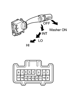
1. INSPECT WIPER AND WASHER SWITCH ASSEMBLY (a) Measure the resistance of the switch. Standard resistance:
If the result is not as specified, replace the switch. |
|
2. INSPECT FRONT WIPER SWITCH ASSEMBLY
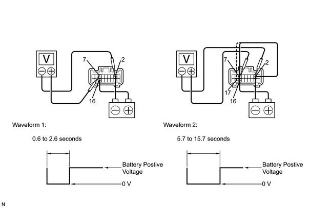
(a) Turn the wiper switch to INF position.
(b) Turn the intermittent time control switch to the FAST position.
(c) Connect the positive (+) lead from the battery to terminal 16 and the negative (-) lead to terminal 2.
(d) Connect the positive (+) lead from the voltmeter to terminal 7 and the negative (-) lead to terminal 2, and check that the meter needle indicates battery voltage.
(e) After connecting terminal 16 to terminal 17, connect to terminal 2 to terminal 17,
(f) Check that the voltage rises from 0 volts to the voltage shown in the table.
|
INT time control switch position |
Voltage |
|---|---|
|
FAST |
Waveform 1 |
|
SLOW |
Waveform 2 |
If operation is not as specified, replace the wiper and washer switch.
|
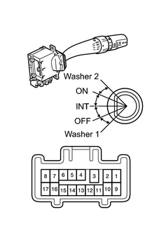
3. INSPECT REAR WIPER AND WASHER SWITCH ASSEMBLY (a) Measure the resistance of the switch. Standard resistance:
If the result is not as specified, replace the switch. |
|

|

|