- VGRS fuse
- VGRS ECU
| Last Modified: 7-3-2017 | 6.8:8.0.40 | Doc ID: RM000001BBR001X |
| Model Year Start: 2007 | Model: LX470 | Prod Date Range: [08/2006 - ] |
| Title: STEERING COLUMN: VARIABLE GEAR RATIO STEERING SYSTEM: C1554/54; EPS Relay Circuit; 2007 MY LX470 [08/2006 - ] | ||
|
DTC |
C1554/54 |
EPS Relay Circuit |
DESCRIPTION
When the VGRS ECU detects a malfunction in the power supply relay (located inside the VGRS ECU), the ECU turns on the warning light, records the DTC, and stops VGRS operation.
|
DTC No. |
DTC Detection Condition |
Trouble Area |
|---|---|---|
|
C1554/54 |
The system detects a malfunction of the power source relay or an open circuit. |
|
WIRING DIAGRAM
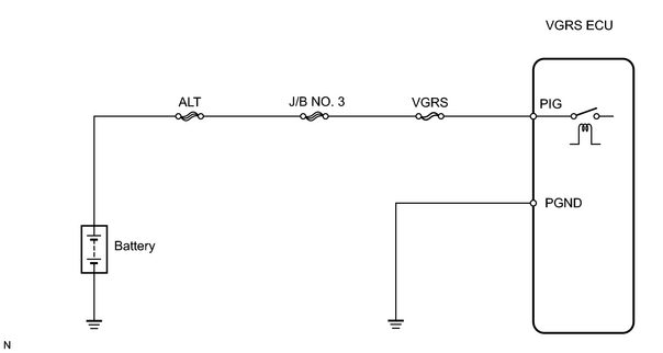
PROCEDURE
|
1. |
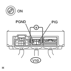
CHECK VOLTAGE BETWEEN TERMINALS PIG AND PGND OF VGRS ECU CONNECTOR |
|
(a) Record and clear VGRS DTCs. (b) Start the engine and measure the voltage between terminals V10-1 (PIG) and V10-2 (PGND) of the VGRS ECU. Result
|
|
| B |

|
| C |
|
|

|
2. |
CHECK VGRS FOR DTC C1554/54 |
(a) Is DTC C1551/54 present?
NOTICE:
Fault may be intermittent. Check harness and connectors carefully and retest.
| YES |
|
| NG |
|

|

|