| Last Modified: 7-3-2017 | 6.8:8.0.40 | Doc ID: RM000001BC0001X |
| Model Year Start: 2007 | Model: LX470 | Prod Date Range: [08/2006 - ] |
| Title: STEERING COLUMN: VARIABLE GEAR RATIO STEERING SYSTEM: VGRS Warning Light Circuit; 2007 MY LX470 [08/2006 - ] | ||
|
VGRS Warning Light Circuit |
DESCRIPTION
If the ECU detects a problem in the VGRS system, the VGRS warning light will illuminate, while at the same time prohibiting VGRS control and recording the DTC in memory.
Connect terminals TC and CG of the DLC3 to make the VGRS warning light blink and output the DTC.
WIRING DIAGRAM
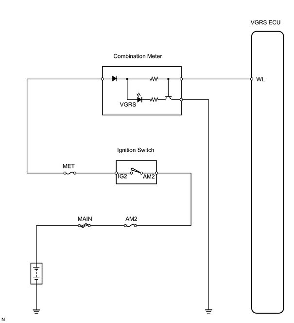
INSPECTION PROCEDURE
PROCEDURE
|
1. |
INSPECT FUSE |
(a) Remove the MET fuse from the cowl side junction block RH.
(b) Measure the resistance of the fuse.
Standard resistance:
Below 1 Ω
| NG |

|
|

|
2. |
CHECK WIRE HARNESS (BATTERY - COMBINATION METER) |
|
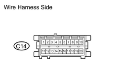
(a) Disconnect the C14 combination meter connector. |
|
(b) Turn the ignition switch ON.
(c) Measure the voltage of the wire harness side connectors.
Standard voltage:
|
Tester Connection |
Condition |
Specified Condition |
|---|---|---|
|
C14-10 - Body ground |
Ignition switch ON |
10 to 14 V |
| NG |
|
|
|
3. |
CHECK WIRE HARNESS (COMBINATION METER - VGRS ECU AND BODY GROUND) |
|
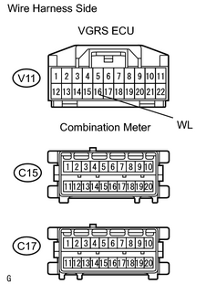
(a) Disconnect the V11 VGRS ECU connector. |
|
(b) Disconnect the C15 and C17 combination meter connectors.
(c) Measure the resistance of the wire harness side connectors.
Standard resistance:
|
Tester Connection |
Specified Condition |
|---|---|
|
WL (V11-16) - C15-9 |
Below 1 Ω |
|
WL (V11-16) - Body ground |
10 k Ω or higher |
|
C17-1 - Body ground |
Below 1 Ω |
| NG |
|
|
|
4. |
CHECK OPERATION OF ECU WITH NEW OR NORMALLY FUNCTIONING ECU |
(a) Temporarily replace the VGRS ECU with a new or normally functioning one.
(b) Check that the malfunction disappears.
OK:
Malfunction disappears
| NG |
|
| OK |
|

|

|