- Open or short in VSV for air injection system circuit (bank 1)
- VSV power source
- VSV for air injection system (bank 1)
- ECM
| Last Modified: 7-3-2017 | 6.8:8.0.40 | Doc ID: RM000001BRE00AX |
| Model Year Start: 2007 | Model: LX470 | Prod Date Range: [08/2006 - ] |
| Title: 2UZ-FE ENGINE CONTROL SYSTEM: SFI SYSTEM: P1440,P1443; Secondary Air Injection Vacuum Switching Valve Circuit Malfunction Bank 1; 2007 MY LX470 [08/2006 - ] | ||
|
DTC |
P1440 |
Secondary Air Injection Vacuum Switching Valve Circuit Malfunction Bank 1 |
|
DTC |
P1443 |
Secondary Air Injection Vacuum Switching Valve Circuit Malfunction Bank 2 |
DESCRIPTION
Refer to DTC P0412
![2007 MY LX470 [08/2006 - ]; 2UZ-FE ENGINE CONTROL SYSTEM: SFI SYSTEM: P0412; Secondary Air Injection System Switching Valve "A" Circuit+](../../../../stylegraphics/info.gif "2007 MY LX470 [08/2006 - ]; 2UZ-FE ENGINE CONTROL SYSTEM: SFI SYSTEM: P0412; Secondary Air Injection System Switching Valve \"A\" Circuit+") .
.
|
DTC No. |
DTC Detection Condition |
Trouble Area |
|---|---|---|
|
P1440 |
AIV1 terminal voltage becomes less than half of the +B voltage while the VSV for air injection system is not operating. (1 trip detection logic) |
|
|
P1443 |
AIV2 terminal voltage becomes less than half of the +B voltage while the VSV for air injection system is not operating. (1 trip detection logic) |
|
MONITOR DESCRIPTION
The ECM detects an open or short in the circuit of the VSV for air injection system according to the AIV1 (AIV2) terminal voltage, stores the DTC, and then illuminates the MIL. When the AIV1 (AIV2) terminal voltage is less than half of the +B voltage while the VSV for air injection system is not operating, the ECM determines it as a malfunction.
MONITOR STRATEGY
|
Related DTCs |
P1440: Secondary air injection system control valve circuit (bank 1) range check P1443: Secondary air injection system control valve circuit (bank 2) range check |
|
Required sensors/components |
VSV for air injection control |
|
Frequency of operation |
Continuous |
|
Duration |
0.5 seconds |
|
MIL operation |
Immediate |
|
Sequence operation |
None |
TYPICAL ENABLING CONDITIONS
All:
|
The monitor will run whenever these DTCs are not present |
- |
P1440:
|
Engine |
Running |
|
No. 2 air switching valve (bank 1) |
Not operating |
P1443:
|
Engine |
Running |
|
No. 2 air switching valve (bank 2) |
Not operating |
TYPICAL MALFUNCTION THRESHOLDS
P1440:
|
No. 2 air switching valve (bank 1) output terminal level |
Low |
P1443:
|
No. 2 air switching valve (bank 2) output terminal level |
Low |
WIRING DIAGRAM
Refer to DTC P0412
.
INSPECTION PROCEDURE
HINT:
Read freeze frame data using the intelligent tester. Freeze frame data records the engine conditions when malfunctions are detected. When troubleshooting, freeze frame data can help determine if the vehicle was running or stopped, if the engine was warmed up or not, if the air fuel ratio was lean or rich, and other data from the time the malfunction occurred.
PROCEDURE
|
1. |
CHECK HARNESS AND CONNECTOR (AIR INJECTION SYSTEM POWER SOURCE) |
|
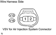
(a) Disconnect the V15 or V16 VSV for air injection system connector. (b) Turn the ignition switch ON. (c) Measure the voltage between terminal 1 of the VSV connector and body ground. Standard: 9 V or more (d) Reconnect the VSV for air injection system connector. |
|
| NG |

|
|

|
2. |
CHECK HARNESS AND CONNECTOR (ECM - VSV FOR AIR INJECTION SYSTEM) |
(a)
Check the harness and connector
.
| NG |
|
|
|
3. |
CHECK VSV (RESISTANCE) |
|
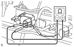
(a) Disconnect the V15 or V16 VSV for air injection system connector. (b) Disconnect the 2 vacuum hoses from the VSV. (c) Measure the resistance of the VSV terminals. Standard resistance:
(d) Reconnect the VSV for air injection system connector. (e) Reconnect the vacuum hose. |
|
| NG |
|
| OK |
|

|

|