| Last Modified: 7-3-2017 | 6.8:8.0.40 | Doc ID: RM000001BU4007X |
| Model Year Start: 2007 | Model: LX470 | Prod Date Range: [08/2006 - ] |
| Title: BRAKE CONTROL: VEHICLE STABILITY CONTROL SYSTEM: TC and CG Terminal Circuit; 2007 MY LX470 [08/2006 - ] | ||
|
TC and CG Terminal Circuit |
DESCRIPTION
Connecting terminals TC and CG of the DLC3 causes the ECU to display the DTC by flashing the ABS warning light and VSC TRAC warning light.
WIRING DIAGRAM
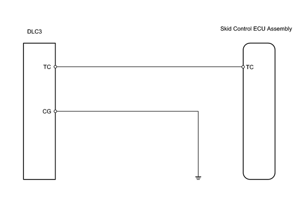
INSPECTION PROCEDURE
PROCEDURE
|
1. |
CHECK DLC3 (TC VOLTAGE) |
|
(a) Turn the ignition switch ON. (b) Measure the voltage between terminals 13 (TC) and 4 (CG) of the DLC3. OK: Standard voltage 10 to 14 V |
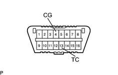
|
| OK |

|
|

|
2. |
CHECK WIRE HARNESS (DLC3 - SKID CONTROL ECU) |
| NG |
|
| OK |
|

|

|