| Last Modified: 7-3-2017 | 6.8:8.0.40 | Doc ID: RM000001BUX003X |
| Model Year Start: 2007 | Model: LX470 | Prod Date Range: [08/2006 - ] |
| Title: NAVIGATION: NAVIGATION SYSTEM: TERMINALS OF ECU; 2007 MY LX470 [08/2006 - ] | ||
TERMINALS OF ECU
1. CHECK MULTI-DISPLAY
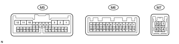
|
Symbols (Terminal No.) |
Wiring Color |
Terminal Description |
Condition |
Specified Condition |
|---|---|---|---|---|
|
GND1 (M5-3) - Body ground |
W-B - Body ground |
Ground |
Always |
Below 1 V |
|
TX1+ (M5-4) - GND1 (M5-3) |
P - W-B |
AVC-LAN communication signal |
Turn ignition switch ON |
2 to 3 V |
|
TX1- (M5-5) - GND1 (M5-3) |
L-B - W-B |
AVC-LAN communication signal |
Turn ignition switch ON |
2 to 3 V |
|
TC (M5-7) - GND1 (M5-3) |
P-B - W-B |
Diagnosis ON signal |
Turn ignition switch ON |
9 to 14 V |
|
IG (M5-10) - GND1 (M5-3) |
B-W - W-B |
Ignition (ON) |
Turn ignition switch OFF |
Below 1 V |
|
IG (M5-10) - GND1 (M5-3) |
B-W - W-B |
Ignition (ON) |
Turn ignition switch ON |
10 to 14 V |
|
ACC (M5-11) - GND1 (M5-3) |
GR - W-B |
Accessory (ON) |
Turn ignition switch OFF |
Below 1 V |
|
ACC (M5-11) - GND1 (M5-3) |
GR - W-B |
Accessory (ON) |
Turn ignition switch ACC or ON |
10 to 14 V |
|
B1 (M5-12) - GND1 (M5-3) |
L-W - W-B |
Battery |
Always |
10 to 14 V |
|
PKB (M5-16) - GND1 (M5-3) |
R-W - W-B |
Parking brake signal |
Turn parking brake switch ON |
Below 1 V |
|
PKB (M5-16) - GND1 (M5-3) |
V - W-B |
Parking brake signal |
Turn parking brake switch OFF |
10 to 14 V |
|
SPD (M5-25) - GND1 (M5-3) |
V - W-B |
Speed signal from combination meter |
See "vehicle signal check mode" |
|
|
SGND (M6-3) - GND1 (M5-3) |
W-B - W-B |
Screen noise or other types of noise occur |
Ignition switch OFF |
Below 1 V |
|
MIN+ (M6-4) - GND1 (M5-3) |
B - W-B |
Microphone voice signal |
See "microphone check" |
- |
|
MIN- (M6-5) - Body ground |
W - Body ground |
Microphone voice signal |
See "microphone check" |
- |
|
MACC (M6-6) - GND1 (M5-3) |
Y-G - W-B |
Microphone Accessory |
Turn ignition switch OFF |
Below 1 V |
|
MACC (M6-6) - GND1 (M5-3) |
Y-G - W-B |
Microphone Accessory |
Turn ignition switch ON |
10 to 14 V |
|
TX3+ (M6-11) - GND1 (M5-3) |
P-L - W-B |
AVC-LAN communication signal |
Turn ignition switch ON |
2 to 3 V |
|
TX3- (M6-12) - GND1 (M5-3) |
P-B - W-B |
AVC-LAN communication signal |
Turn ignition switch ON |
2 to 3 V |
|
TX+ (M6-13) - GND1 (M5-3) |
P - W-B |
AVC-LAN communication signal |
Turn ignition switch ON |
2 to 3 V |
|
TX- (M6-14) - GND1 (M5-3) |
L - W-B |
AVC-LAN communication signal |
Turn ignition switch ON |
2 to 3 V |
|
SGND (M6-17) - GND1 (M5-3) |
Shielded - W-B |
Screen noise or other types of noise occur |
Ignition switch OFF |
Below 1 V |
|
MCO+ (M6-18) - GND1 (M5-3) |
B - W-B |
Microphone voice signal |
See "microphone check" |
- |
|
MCO- (M6-19) - GND1 (M5-3) |
W - W-B |
Microphone voice signal |
See "microphone check" |
- |
|
IVO+ (M6-21) - GND1 (M5-3) |
O - W-B |
Telephone voice signal (bluetooth) |
See "microphone check" |
- |
|
IVO- (M6-22) - GND1 (M5-3) |
W - W-B |
Telephone voice signal (bluetooth) |
See "microphone check" |
- |
|
VR - (M6-23) - GND1 (M5-3) |
B - W-B |
Video return signal |
Turn ignition switch OFF |
Below 1 V |
|
R - (M6-24) - GND1 (M5-3) |
Y - W-B |
Display signal (red) |
Navigation display is on |
Pulse generation *2 |
|
G - (M6-25) - GND1 (M5-3) |
W - W-B |
Display signal (green) |
Navigation display is on |
Pulse generation *2 |
|
B - (M6-26) - GND1 (M5-3) |
R - W-B |
Display signal (blue) |
Navigation display is on |
Pulse generation *2 |
|
SYNC (M6-27) - GND1 (M5-3) |
G - W-B |
Display signal (synchronize) |
Navigation display is on |
Pulse generation *1 |
|
VG (M6-28) - Body ground |
Shielded - Body ground |
Shielded ground |
Always |
Below 1 V |
|
NTSC (M7-1) - GND1 (M5-3) |
W - W-B |
DVD screen is in disorder |
Ignition switch ON and DVD displayed |
Pulse generation *3 |
|
SGD1 (M7-4) - GND1 (M5-3) |
B - W-B |
Screen noise or other types of noise occur |
Ignition switch OFF |
Below 1 V |
|
SGND (M7-5) - GND1 (M5-3) |
Shielded - W-B |
Screen noise or other types of noise occur |
Ignition switch OFF |
Below 1 V |
-
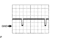 *1: Oscilloscope wave
Terminal to be measured: SYNC - GND1
Setting for measurement: 500 mV/DIV., 10 - μsec./DIV.,
Condition: Navigation map is displayed.
-
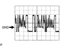 *2: Oscilloscope wave
Terminal to be measured: R, G, B - GND1
Setting for measurement: 200 mV/DIV., 10 - μsec./DIV.,
Condition: Navigation map is switched.
-
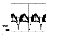 *3: Oscilloscope wave
Terminal to be measured: NTSC - SGD1
Setting for measurement: 0.2 mV/DIV., 0.2 μsec./DIV.,
Condition: Ignition switch ON and DVD displayed.
2. CHECK NAVIGATION ECU
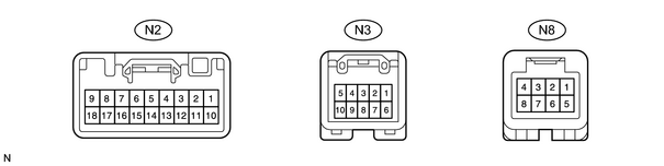
|
Symbols (Terminal No.) |
Wiring Color |
Terminal Description |
Condition |
Specified Condition |
|---|---|---|---|---|
|
AUI+ (N2-1) - GND (N2-17) |
P - W-B |
Sound signal (input) |
Audio system is playing |
- |
|
AUO+ (N2-2) - GND (N2-17) |
P - W-B |
Sound signal (output) |
Audio system is playing |
- |
|
SLD1 (N2-3) - Body ground |
Shielded - Body ground |
Shielded ground |
Always |
Below 1.0 V |
|
SPD (N2-5) - GND1 (N2-17) |
V - W-B |
Speed signal from combination meter |
See "Vehicle Signal Check Mode" |
- |
|
+B (N2-9) - GND (N2-17) |
L-Y - W-B |
Battery |
Always |
10 to 14 V |
|
AUI- (N2-10) - GND (N2-17) |
V - W-B |
Sound signal (input) |
Audio system is playing |
- |
|
AUO- (N2-10) - GND (N2-17) |
V - W-B |
Sound signal (output) |
Audio system is playing |
- |
|
VOI+ (N2-12) - Body ground |
O - Body ground |
Telephone voice signal (bluetooth) |
See "microphone check" |
- |
|
VOI- (N2-13) - Body ground |
W - Body ground |
Telephone voice signal (bluetooth) |
See "microphone check" |
- |
|
REV (N2-10) - GND (N2-17) |
R-B - W-B |
Reverse signal from combination meter |
See "Vehicle Signal Check Mode" |
- |
|
GND (N2-17) - Body ground |
W-B - Body ground |
Ground |
Always |
Below 1 V |
|
ACC (N2-18) - GND (N2-17) |
GR - W-B |
Accessory (ON) |
Turn ignition switch OFF |
Below 1 V |
|
ACC (N2-18) - GND (N2-17) |
GR - W-B |
Accessory (ON) |
Turn ignition switch ACC or ON |
10 to 14 V |
|
VR - (N3-1) - GND (N2-17) |
B - W-B |
Video return signal |
Turn ignition switch OFF |
Below 1 V |
|
R - (N3-2) - GND (N2-17) |
Y - W-B |
Display signal (red) |
Navigation display is on |
Pulse generation *2 |
|
B - (N3-3) - GND (N2-17) |
R - W-B |
Display signal (blue) |
Navigation display is on |
Pulse generation *2 |
|
TX+ (N3-5) - GND (N2-17) |
P - W-B |
AVC-LAN communication signal |
Turn ignition switch to ACC |
2 to 3 V |
|
VG (N3-6) - Body ground |
Shielded - Body ground |
Shielded ground |
Always |
Below 1 V |
|
G - (N3-7) - GND (N2-17) |
W - W-B |
Display signal (green) |
Navigation display is on |
Pulse generation *2 |
|
SYNC (N3-8) - GND (N2-17) |
G - W-B |
Display signal (synchronize) |
Navigation display is on |
Pulse generation *1 |
|
TX- (N3-10) - GND (N2-17) |
L-B - W-B |
AVC-LAN communication signal |
Turn ignition switch to ACC |
2 to 3 V |
|
MIC+ (N8-3) - GND (N2-17) |
B - W-B |
Microphone voice signal |
See "microphone check" |
- |
|
MIC- (N8-5) - GND (N2-17) |
W - W-B |
Microphone voice signal |
See "microphone check" |
- |
|
SNSE (N8-7) - Body ground |
W-B - Body ground |
Ground |
Always |
Below 1 V |
-
*1: Oscilloscope wave
Terminal to be measured: SYNC - GND1
Setting for measurement: 500 mV/DIV., 10 μsec./DIV.,
Condition: Navigation map is displayed.
-
*2: Oscilloscope wave
Terminal to be measured: R, G, B - GND1
Setting for measurement: 200 mV/DIV., 10 μsec./DIV.,
Condition: Navigation map is switched.
3. CHECK RADIO RECEIVER ASSEMBLY
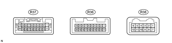
|
Symbols (Terminals No.) |
Condition |
Specified Condition |
Problem symptoms when short circuit is detected. |
|---|---|---|---|
|
B - GND (R37-1 - R37-20) |
Always |
10 to 14 V |
Audio system does not operate. |
|
AMP - GND (R37-3 - R37-20) |
- |
- |
- |
|
MUTE - GND (R37-7 - R37-20) |
- |
- |
"Pop" sound, etc. |
|
Audio system does not operate. |
|||
|
R+ - GND (R37-8 - R37-20) |
Always |
10 to 14 V |
Sound from front right speaker is low. |
|
L+ - GND (R37-9 - R37-20) |
Always |
10 to 14 V |
Sound from front left speaker is low. |
|
ACC - GND (R37-11 - R37-20) |
Ignition switch ACC |
10 to 14 V |
Audio system does not operate. |
|
ANT+ - GND (R37-13 - R37-20) |
Radio switch ON |
10 to 14 V |
Antenna does not extend. |
|
RR - GND (R37-18 - R37-20) |
Always |
10 to 14 V |
Sound from rear right speaker is low. |
|
RL - GND (R37-19 - R37-20) |
Always |
10 to 14 V |
Sound from rear left speaker is small. |
|
GND - Body ground (R37-20 - Body ground) |
Always |
Below 1 V |
Audio system is normal. |
|
CDR+ (R38-2) |
- |
- |
Sound from right side speaker is low. |
|
CDR- (R38-3) |
- |
- |
Sound from right side speaker is low. |
|
CDL+ (R38-4) |
- |
- |
Sound from left side speaker is low. |
|
CDL- (R38-5) |
- |
- |
Sound from left side speaker is low. |
|
MUTE - GND (R37-7 - R37-20) |
- |
- |
"Pop" sound, etc. |
|
Audio system does not operate. |
|||
|
TX+ - GND (R38-9 - R37-20) |
AVC-LAN communication circuit |
- |
Audio system does not operate. |
|
TX- (R38-10) |
AVC-LAN communication circuit |
- |
Audio system does not operate. |
|
TX+ (R36-9) |
AVC-LAN communication circuit |
- |
Audio system does not operate. |
|
TX- (R36-10) |
AVC-LAN communication circuit |
- |
Audio system does not operate. |
4. CHECK STEREO COMPONENT AMPLIFIER
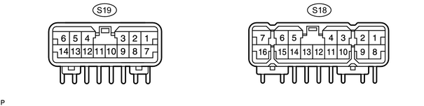
|
Symbols (Terminal No.) |
Condition |
Specified Condition |
Problem symptoms when short circuit is detected. |
|---|---|---|---|
|
FR+ - E (S18-1 - S18-12) |
Radio switch ON |
5 to 7 V |
RH side speaker does not sound. |
|
FL+ - E (S18-2 - S18-12) |
Radio switch ON |
5 to 7 V |
LH side speaker does not sound. |
|
RR+ - E (S18-3 - S18-12) |
Radio switch ON |
5 to 7 V |
Rear RH side speaker does not sound. |
|
RL+ - E (S18-4 - S18-12) |
Radio switch ON |
5 to 7 V |
Rear LH side speaker does not sound. |
|
WFR+ - E (S18-5 - S18-12) |
Radio switch ON |
5 to 7 V |
Rear RH side speaker does not sound. |
|
WFL+ - E (S18-6 - S18-12) |
Radio switch ON |
5 to 7 V |
Rear LH side speakers do not sound. |
|
+B - E (S18-7 - S18-12) |
Always |
10 to 14 V |
All speakers do not sound. |
|
FR- - E (S18-8 - S18-12) |
Radio switch ON |
5 to 7 V |
RH side speaker does not sound. |
|
FL- - E (S18-9 - S18-12) |
Radio switch ON |
5 to 7 V |
LH side speaker does not sound. |
|
RR- - E (S18-10 - S18-12) |
Radio switch ON |
5 to 7 V |
Rear RH side speaker does not sound. |
|
RL- - E (S18-11 - S18-12) |
Radio switch ON |
5 to 7 V |
Rear LH side speaker does not sound. |
|
E - Body ground (S18-12 - Body ground) |
Always |
Below 1 V |
- |
|
GND2 - Body ground (S18-13 - Body ground) |
Always |
Below 1 V |
- |
|
WFR- - E (S18-14 - S18-12) |
Radio switch ON |
5 to 7 V |
Rear RH side speaker does not sound. |
|
WFL- - E (S18-15 - S18-12) |
Radio switch ON |
5 to 7 V |
Rear LH side speaker does not sound. |
|
+B2 - GND2 (S18-16 - S18-13) |
Always |
10 to 14 V |
All speakers do not sound. |
|
AMP (S19-1) |
- |
- |
- |
|
ACC - GND2 (S19-2 - S18-13) |
Ignition switch ACC |
10 to 14 V |
Audio system does not operate. |
|
BEEP (S19-4) |
- |
- |
LH side speaker does not sound. |
|
FL - GND2 (S19-5 - S18-13) |
Always |
10 to 14 V |
Sound from front LH speaker is low. |
|
FR - GND2 (S19-6 - S18-13) |
Always |
10 to 14 V |
Sound from front RH speaker is low. |
|
SGND - GND2 (S19-11 - S18-13) |
- |
5 to 7 V |
- |
|
MUTE - GND2 (S19-12 - S18-13) |
Radio switch ON |
5 to 7 V |
Audio system does not operate. |
|
RL - GND2 (S19-13 - S18-13) |
Always |
10 to 14 V |
Sound from rear LH speaker is low. |
|
RR - GND2 (S19-2 - S18-13) |
Always |
10 to 14 V |
Sound from rear RH speaker is low. |
5. CHECK DISC PLAYER CHANGER

|
Symbols (Terminal No.) |
Condition |
Specified Condition |
Problem symptoms when short circuit is detected. |
|---|---|---|---|
|
ACC - GND (D32-1 - D32-20) |
Ignition switch ACC |
10 to 14 V |
Disc player changer does not operate. |
|
TXM+ - GND (D32-3 - D32-20) |
AVC-LAN communication circuit |
- |
Audio system does not operate. |
|
CDR+ (D32-5) |
- |
- |
Sound from right side speaker is low. |
|
CDL+ (D32-6) |
- |
- |
Sound from left side speaker is low. |
|
NTSC (D32-9) |
- |
- |
- |
|
+B - GND (D32-10 - D32-20) |
Always |
10 to 14 V |
Disc player changer does not operate. |
|
MUTE - GND (D32-11 - D32-20) |
DISC switch ON |
5 to 7 V |
Audio system does not operate. |
|
TXM- - GND (D32-13 - D32-20) |
AVC-LAN communication circuit |
- |
Audio system does not operate. |
|
CDR- (D32-15) |
- |
- |
Sound from right side speaker is low. |
|
CDL- (D32-16) |
- |
- |
Sound from left side speaker is low. |
6. CHECK NETWORK GATEWAY ECU
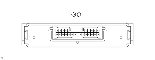
|
Symbols (Terminal No.) |
Wiring Color |
Condition |
Specified Condition |
|---|---|---|---|
|
IG - GND (G5-2 - G5-14) |
B-W - W-B |
Ignition switch ON |
10 to 14 V |
|
MPD1 (G5-4) |
B |
Communication circuit (Gateway ECU and Center ECU) |
- |
|
GTX+ (G5-5) |
P - L |
AVC-LAN communication circuit |
- |
|
CG - Body ground (G5-7 - Body ground) |
BR - Body ground |
Always |
Below 1 V |
|
BATT - GND (G5-8 - G5-14) |
L-W - W-B |
Always |
10 to 14 V |
|
MPD2 (G5-11) |
P - B |
Communication circuit (Gateway ECU and Center ECU) |
- |
|
GTX- (G5-12) |
P - B |
AVC-LAN communication circuit |
- |
|
GND - Body ground (G5-7 - Body ground) |
BR - Body ground |
Always |
Below 1 V |
-
*1: Oscilloscope wave
Terminal to be measured: SYNC - GND1
Setting for measurement: 500 mV/DIV., 10 μsec./DIV.,
Condition: Navigation display is ON.
-
*2: Oscilloscope wave
Terminal to be measured: R, G, B - GND1
Setting for measurement: 200 mV/DIV., 10 μsec./DIV.,
Condition: Navigation map is switched ON.

|

|