| Last Modified: 7-3-2017 | 6.8:8.0.40 | Doc ID: RM000001BYF008X |
| Model Year Start: 2007 | Model: LX470 | Prod Date Range: [08/2006 - ] |
| Title: STEERING COLUMN: STEERING COLUMN ASSEMBLY: REASSEMBLY; 2007 MY LX470 [08/2006 - ] | ||
REASSEMBLY
NOTICE:
When using a vise, do not over tighten it.
1. APPLY MOLYBDENUM DISULFIDE LITHIUM BASE GREASE TO PARTS INDICATED BY ARROWS
![2007 MY LX470 [08/2006 - ]; STEERING COLUMN: STEERING COLUMN ASSEMBLY: COMPONENTS](../../../../stylegraphics/info.gif "2007 MY LX470 [08/2006 - ]; STEERING COLUMN: STEERING COLUMN ASSEMBLY: COMPONENTS")
|
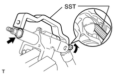
2. INSTALL STEERING MAIN SHAFT ASSEMBLY (a) Install the bearing thrust collar and compression spring to the shaft. (b) Install the shaft to the column upper tube. (c) Using SST, compress the compression spring. SST: 09950-40011 09958-04011 NOTICE: Do not bend the universal joint of the shaft more than 20°. (d) Using a snap ring expander, install a new snap ring to the shaft. |
|
3. INSTALL COLUMN UPPER TUBE SUB-ASSEMBLY WITH MAIN SHAFT ASSEMBLY
(a) Install the 3 bushings to the break away bracket.
(b) Install the 2 new support stopper bolt bushings to the column tube.
(c) Install the column upper tube to the break away bracket.
(d) Install the column upper tube with the main shaft to the break away bracket.
(e) Using a hexagon wrench, install the 2 tilt steering bolts.
Torque:
20 N·m {210 kgf·cm, 15ft·lbf}
(f) Install a new snap ring.
4. INSTALL TELESCOPIC STEERING SCREW
(a) Install the 4 energy absorber cushions, 2 bearings and telescopic steering screw.
(b) Install the nut.
Torque:
0.8 N·m {8.2 kgf·cm, 7.1in·lbf}
(c) Using a punch, stake the nut.
5. INSTALL STEERING COLUMN BRACKET SPACER
6. INSTALL TELESCOPIC STEERING SLIDER
7. INSTALL TELESCOPIC STEERING BUSH
8. INSTALL TELESCOPIC STEERING SLIDER SUPPORT
(a) Install the telescopic steering slider support with the 2 bolts.
Torque:
11 N·m {110 kgf·cm, 8ft·lbf}
|
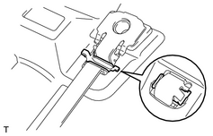
9. INSTALL STEERING ENERGY ABSORBING GUIDE, PLATE AND CLIP (a) Install the 2 new energy absorbing guides and 2 new absorbing plates. (b) Install the 2 new energy absorbing clips. |
|
10. INSTALL STEERING COLUMN TUBE SUPPORT
(a) Install the tube attachment to the column tube support.
(b) Install the column tube support with the bolt.
Torque:
15 N·m {150 kgf·cm, 11ft·lbf}
|
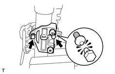
11. INSTALL COLUMN UPPER BRACKET AND COLUMN UPPER CLAMP (a) Install the 2 telescopic steering wedge lock springs, 2 steering lock wedges and column upper bracket and column upper clamp. (b) Using a hexagon wrench, install the 2 telescopic lever lock bolts. Torque: 10 N·m {100 kgf·cm, 7ft·lbf} (c) Install and tighten the 2 new tapered-head bolts until the bolt heads break off. (d) Install the column tube stopper. Torque: 19 N·m {190 kgf·cm, 14ft·lbf} |
|
12. INSTALL POWER TELESCOPIC MOTOR
(a) Install the telescopic steering column cable.
(b) Install the power telescopic motor with the 2 bolts.
Torque:
9.0 N·m {90 kgf·cm, 78in·lbf}
13. INSTALL NO. 1 TILT STEERING ADJUSTING NUT
(a) Install 2 new support stopper bolt bushings to the No. 1adjusting nut.
(b) Install the No. 1 adjusting nut to the column upper tube.
(c) Install the 2 tilt steering shafts.
14. INSTALL POWER TILT MOTOR
(a) Install 2 new support stopper bolt bushings to the power tilt motor.
(b) Install 2 new E-rings.
(c) Using a hexagon wrench, install the power tilt motor and 2 tilt steering bolts.
Torque:
20 N·m {210 kgf·cm, 15ft·lbf}
(d) Install the stopper No. 1 and stopper spring.
(e) Using a hexagon wrench, install the support stopper bolt.
15. INSTALL TURN SIGNAL BRACKET
(a) Install the turn signal bracket with the 3 bolts.
16. INSTALL NO. 1 STEERING COLUMN PROTECTOR
(a) Install the No. 1 steering column protector with the bolt.
17. INSTALL CONNECTOR BRACKET
(a) Install the connector bracket with the bolt.
18. INSTALL TRANSPONDER KEY AMPLIFIER
19. INSTALL NO. 2 LOWER COVER
20. INSTALL VGRS ACTUATOR ASSEMBLY
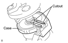
NOTICE:
Pull out the key from the key cylinder and lock the main shaft.
(a) Turn the case clockwise by hand until it becomes harder to turn the cable.
(b) Then rotate the case counterclockwise about 2.5 turns to align the cutout.
HINT:
The cable will rotate about 2.5 turns to either the left or right of the center.
NOTICE:
After setting, be careful not to rotate the VGRS actuator until the installation of the steering column.
|
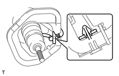
(c) Install the boot with plate to the VGRS actuator and connect the wire harness clamp to the plate. |
|
(d) Install the thrust stopper, No. 2 lower cover and boot clamp to the main shaft.
(e) Align the matchmarks on the VGRS actuator and main shaft.
(f) Install the bolt.
Torque:
34 N·m {350 kgf·cm, 25ft·lbf}
(g) Install the boot to the No. 2 lower cover and clamp.

|

|