| Last Modified: 7-3-2017 | 6.8:8.0.40 | Doc ID: RM000001CFV004X |
| Model Year Start: 2007 | Model: LX470 | Prod Date Range: [08/2006 - ] |
| Title: AIR CONDITIONING: AIR CONDITIONING SYSTEM: DIAGNOSIS SYSTEM; 2007 MY LX470 [08/2006 - ] | ||
DIAGNOSIS SYSTEM
1. LIST OF OPERATION METHODS
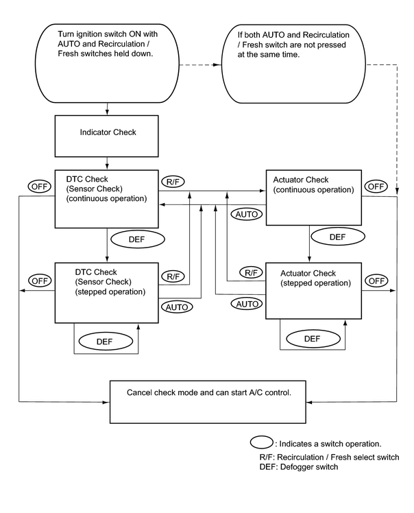
(a) By operating each of the A/C control switches as shown in the diagram below, it is possible to enter the diagnosis check mode.
2. CHECK DLC3
|
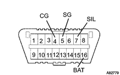
(a) The ECM uses ISO 15765-4 for communication. The terminal arrangement of the DLC3 complies with SAE J1962 and matches the ISO 15765-4 format.
|
|

|

|