- Front height control sensor RH
- Suspension control ECU
- Wire harness
| Last Modified: 7-3-2017 | 6.8:8.0.40 | Doc ID: RM000001CTY004X |
| Model Year Start: 2007 | Model: LX470 | Prod Date Range: [08/2006 - ] |
| Title: SUSPENSION CONTROL: ACTIVE HEIGHT CONTROL SUSPENSION: C1711-C1713/13; Front Height Control Sensor RH Circuit Malfunction; 2007 MY LX470 [08/2006 - ] | ||
|
DTC |
C1711 |
Front Height Control Sensor RH Circuit Malfunction |
|
DTC |
C1712 |
Front Height Control Sensor LH Circuit Malfunction |
|
DTC |
C1713/13 |
Rear Height Control Sensor Circuit Malfunction |
DESCRIPTION
Inside each sensor, a brush integrated with the control sensor rotor shaft moves above the resister, providing linear output. The resistance value between the brush and resistor terminal changes in proportion to the shaft rotation angle, so the fixed voltage applied to the resistor by the ECU is modified by the sensor and output to the ECU as a voltage indication the shaft rotation angle.
|
DTC No. |
DTC Detection Condition |
Trouble Area |
|---|---|---|
|
C1711/11 |
When the following condition is consisting and the abnormal signal continued for 1 sec. at the vehicle speed 8 km/h (5 mph) or more: Detecting the abnormal signal (Height control sensor terminal voltage of ECU is 0.3 V or less or 4.7 V or more) for every 0.01 sec. and that continued for 0.2 sec. |
|
|
C1712/12 |
When the following condition is consisting and the abnormal signal continued for 1 sec. at the vehicle speed 8 km/h (5 mph) or more: Detecting the abnormal signal (Height control sensor terminal voltage of ECU is 0.3 V or less or 4.7 V or more) for every 0.01 sec. and that continued for 0.2 sec. |
|
|
C1713/13 |
When the following condition is consisting and the abnormal signal continued for 1 sec. at the vehicle speed 8 km/h (5 mph) or more: Detecting the abnormal signal (Height control sensor terminal voltage of ECU is 0.3 V or less or 4.7 V or more) for every 0.01 sec. and that continued for 0.2 sec. |
|
HINT:
- DTC C1711/11 corresponds to the front height control sensor RH circuit.
- DTC C1712/12 corresponds to the front height control sensor LH circuit.
- DTC C1713/13 corresponds to the rear height control sensor circuit.
Fail-safe function:
If a trouble occurs in the height control sensor circuit, the height control is prohibited after the ECU has adjusted the vehicle height to the standard (fluid pressure correspond to the standard height).
WIRING DIAGRAM
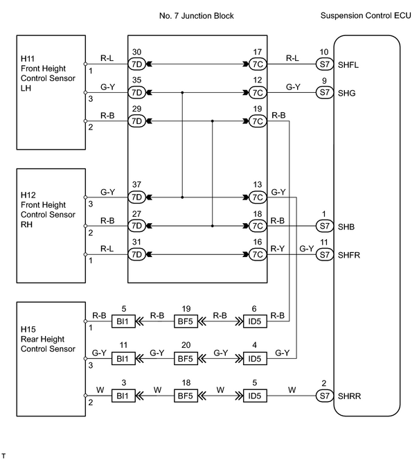
INSPECTION PROCEDURE
HINT:
When using the intelligent tester, start from *1. When not using the intelligent tester, start from *2.
PROCEDURE
|
1. |
READ VALUE USING INTELLIGENT TESTER (HEIGHT CONTROL SENSOR)*1 |
(a) Connect the intelligent tester (with CAN VIM) to the DLC3.
(b) Turn the ignition switch ON and push the intelligent tester main switch ON.
(c) Select the DATA LIST mode on the intelligent tester.
(d) Check that the vehicle height value of the height control sensor displayed by the intelligent tester is changing when pushing the UP or DOWN button of the height select switch.
OK:
Vehicle height value must be changing.
| NG |

|
| OK |
|
|
2. |
CHECK SUSPENSION CONTROL ECU*2 |
|
(a) Remove the suspension control ECU with connectors still connected. |
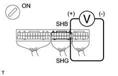
|
(b) Turn the ignition switch ON.
(c) Measure the voltage between terminals SHB and SHG of the suspension control ECU connector.
Standard voltage:
|
Tester Connection |
Specified Condition |
|---|---|
|
S7-1 (SHB) - S7-9 (SHG) |
Approximately 5 V |
| NG |
|
|

|
3. |
INSPECT HEIGHT CONTROL SENSOR (FRONT RH, FRONT LH AND REAR) |
|
(a) Disconnect the height control sensor connector. |
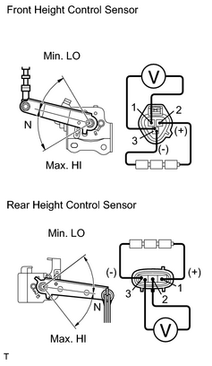
|
(b) Remove the height control sensor.
(c) Connect 3 dry batteries of 1.5 V in series.
(d) Connect terminal 2 to the batteries' positive (+) terminal, and terminal 3 to the batteries' negative (-) terminal, then apply voltage about 4.5 V between terminals 2 and 3.
(e) Measure the voltage between terminals 1 and 3 when the height control sensor link is slowly moved up and down.
Standard voltage:
|
Tester Connection |
Sensor Link Position |
Specified Condition |
|---|---|---|
|
1 - 3 |
Max. HI |
Approximately 4.05 V |
|
1 - 3 |
N |
Approximately 2.25 V |
|
1 - 3 |
Min. LO |
Approximately 0.45 V |
(f) Disconnect the height control sensor connector.
(g) Remove the height control sensor.
(h) Connect 3 dry batteries of 1.5 V in series.
(i) Connect terminal 1 to the batteries' positive (+) terminal, and terminal 3 to the batteries' negative (-) terminal, then apply voltage about 4.5 V between terminals 1 and 3.
(j) Measure the voltage between terminals 2 and 3, when the height control sensor link is slowly moved up and down.
Standard voltage:
|
Tester Connection |
Sensor Link Position |
Specified Condition |
|---|---|---|
|
2 - 3 |
Max. HI |
Approximately 4.05 V |
|
2 - 3 |
N |
Approximately 2.25 V |
|
2 - 3 |
Min. LO |
Approximately 0.45 V |
| NG |
|
|
|
4. |
CHECK WIRE HARNESS (HEIGHT CONTROL SENSOR (FRONT RH, FRONT LH AND REAR) - SUSPENSION CONTROL ECU) |
| NG |
|
| OK |
|

|

|