- When the condition that the B terminal voltage of ECU is more than 10 +- 0.5 V and the lower reaches voltage of the solenoid while it is in non-operation condition is less than 20% of the B terminal voltage continued for 20 +- 5 msec.
- When the condition that the B terminal voltage of ECU is more than 10 +- 0.5 V and the lower reaches voltage of the solenoid while it is in operation condition is more than 80% of the B terminal voltage continued for 20 +- 5 msec.
| Last Modified: 7-3-2017 | 6.8:8.0.40 | Doc ID: RM000001CU7004X |
| Model Year Start: 2007 | Model: LX470 | Prod Date Range: [08/2006 - ] |
| Title: SUSPENSION CONTROL: ACTIVE HEIGHT CONTROL SUSPENSION: C1731/31-C1734/34,C1736/36; Front Height Control Gate Solenoid Valve Circuit Malfunction; 2007 MY LX470 [08/2006 - ] | ||
|
DTC |
C1731/31 |
Front Height Control Gate Solenoid Valve Circuit Malfunction |
|
DTC |
C1732/32 |
Front Height Control Leveling Solenoid Valve Circuit Malfunction |
|
DTC |
C1733/33 |
Rear Height Control Gate Solenoid Valve Circuit Malfunction |
|
DTC |
C1734/34 |
Rear Height Control Leveling Solenoid Valve Circuit Malfunction |
|
DTC |
C1736/36 |
Accumulator Solenoid Valve Circuit Malfunction |
DESCRIPTION
The control valve assembly consists of each front and rear leveling valve and gate valve. It performs the height control and connecting and disconnecting the fluid line of the right and left shock absorber by operating the solenoid valve ON and OFF with the control signal from the ECU.
|
DTC No. |
DTC Detection Condition |
Trouble Area |
|---|---|---|
|
C1731/31 |
When either of the following condition consisted 4 times continuously: |
|
|
C1732/32 |
When either of the following condition consisted 4 times continuously:
|
|
|
C1733/33 |
When either of the following condition consisted 4 times continuously:
|
|
|
C1734/34 |
When either of the following condition consisted 4 times continuously:
|
|
|
C1736/36 |
When either of the following condition consisted 4 times continuously:
|
|
HINT:
- DTC C1731/31 corresponds to the front gate valve solenoid circuit.
- DTC C1732/32 corresponds to the front leveling valve solenoid circuit.
- DTC C1733/33 corresponds to the rear gate valve solenoid circuit.
- DTC C1734/34 corresponds to the rear leveling valve solenoid circuit.
- DTC C1736/36 corresponds to the height control accumulator solenoid circuit.
Fail-safe function:
If a trouble occurs in the control valve assembly circuit, the ECU prohibits the height control and fixed the damping force at the sports mode.
WIRING DIAGRAM
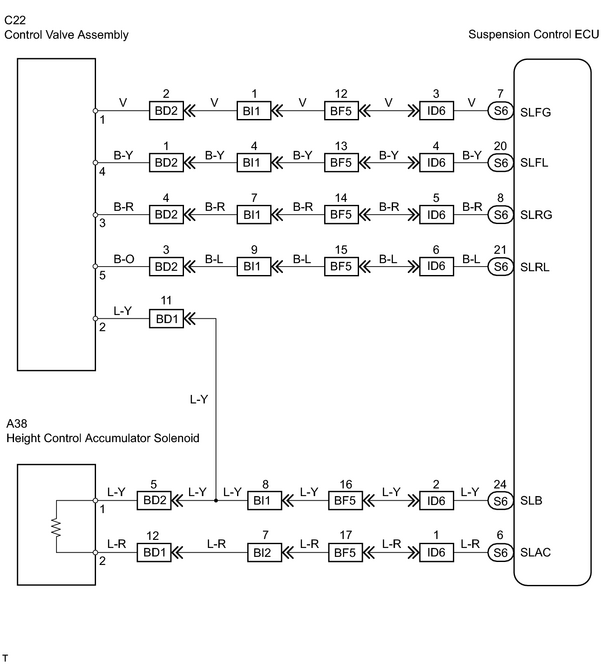
INSPECTION PROCEDURE
HINT:
When using the intelligent tester, start from *1. When not using the intelligent tester, start from *2.
PROCEDURE
|
1. |
PERFORM ACTIVE TEST USING INTELLIGENT TESTER (CONTROL VALVE ASSEMBLY AND HEIGHT CONTROL ACCUMULATOR SOLENOID)*1 |
(a) Connect the intelligent tester (with CAN VIM) to the DLC3.
(b) Start the engine and push the intelligent tester main switch ON.
(c) Select the ACTIVE TEST mode on the intelligent tester.
(d) Check that the operation sound of the solenoid or vibration of the control valve assembly and height control accumulator when operating the solenoid with the intelligent tester.
OK:
The operation sound of the solenoid should be heard or the vibration of the control valve solenoid or height control accumulator should be felt.
| NG |

|
| OK |
|
|
2. |
CHECK SUSPENSION CONTROL ECU*2 |
|
(a) Using SST, connect terminals 12 (TS) and 4 (CG) of the DLC3. |
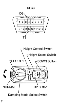
|
SST: 09843-18040
(b) Push the DOWN button of the height select switch 5 times or more within 5 seconds after starting the engine.
HINT:
At this time the height control OFF indicator light flashes at 0.25 second intervals.
(c) Perform each solenoid inspection by the switches of the following table, then check that the operation sound of the solenoid or the vibration of the control valve or height control accumulator.
|
Item |
Damping mode select switch |
Height control switch |
Height select switch |
|---|---|---|---|
|
Front leveling solenoid |
SPORT 1 mode |
- |
Push UP button |
|
Rear leveling solenoid |
SPORT 1 mode |
- |
Push DOWN button |
|
Front gate solenoid |
SPORT 1 mode |
Push and hold |
Push UP button |
|
Rear gate solenoid |
SPORT 1 mode |
Push and hold |
Push DOWN button |
|
Height control accumulator solenoid |
NORMAL mode |
- |
Push UP button |
OK:
The operation sound of the solenoid should be heard of the vibration of the control valve solenoid or height control accumulator should be felt.
| OK |
|
|

|
3. |
CHECK WIRE HARNESS (SUSPENSION CONTROL ECU - CONTROL VALVE ASSEMBLY AND ACCUMULATOR) |
| NG |
|
|
|
4. |
INSPECT CONTROL VALVE SOLENOID AND HEIGHT CONTROL ACCUMULATOR SOLENOID |
|
(a) Disconnect the control valve connector. |
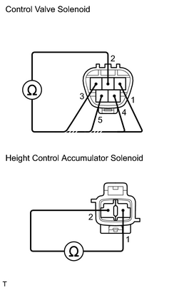
|
(b) Measure the resistance between terminals 2 and 1, 3, 4, 5 of the control valve connector.
Standard resistance:
|
Tester Connection |
Specified Condition |
|---|---|
|
1 - 2 |
3.0 to 3.8 Ω |
|
2 - 3 |
3.0 to 3.8 Ω |
|
2 - 4 |
3.0 to 3.8 Ω |
|
2 - 5 |
3.0 to 3.8 Ω |
(c) Disconnect the accumulator solenoid connector from the height control accumulator.
(d) Measure the resistance between terminals 1 and 2 of the accumulator solenoid connector.
Standard resistance:
|
Tester Connection |
Specified Condition |
|---|---|
|
1 - 2 |
3.0 to 3.6 Ω |
| NG |
|
REPLACE CONTROL VALVE ASSEMBLY OR HEIGHT CONTROL ACCUMULATOR SOLENOID |
| OK |
|

|

|