- Control valve assembly
- Fluid pressure sensor
- Fluid clog in the fluid line or each solenoid valve
- Suspension control ECU
- Wire harness
| Last Modified: 7-3-2017 | 6.8:8.0.40 | Doc ID: RM000001CUA004X |
| Model Year Start: 2007 | Model: LX470 | Prod Date Range: [08/2006 - ] |
| Title: SUSPENSION CONTROL: ACTIVE HEIGHT CONTROL SUSPENSION: C1763/63,C1764/64; Abnormal Oil Pressure due to not Opening Leveling Valve; 2007 MY LX470 [08/2006 - ] | ||
|
DTC |
C1763/63 |
Abnormal Oil Pressure due to not Opening Leveling Valve |
|
DTC |
C1764/64 |
Abnormal Oil Pressure due to not Opening Accumulator Valve |
DESCRIPTION
|
DTC No. |
DTC Detection Condition |
Trouble Area |
|---|---|---|
|
C 1763/63 |
When the pump and motor is ON and the pump delivery pressure has exceeded 15.8 MPa continuously for 0.3 sec. |
|
|
C 1764/64 |
When the pump and motor is ON and the pump delivery pressure has exceeded 15.8 MPa continuously for 0.3 sec. |
|
Fail-safe function:
-
If the DTC C1763/63 detected, the height control is prohibited after the following controls are performed.
- In case that the height of the defect wheel is -10 to +10 mm against the other wheels, adjust the normal wheels to the standard height.
- In case that the height of the defect wheel is more than 10 mm higher than the other wheels, adjust the normal wheels 10 mm higher.
- In case that the height of the defect wheel is less than 10 mm lower than the other wheels, adjust the normal wheels 10 mm lower.
- If the DTC C1764/64 detected, the ECU prohibits the control of accumulating the releasing of the pressure of the height control accumulator.
WIRING DIAGRAM
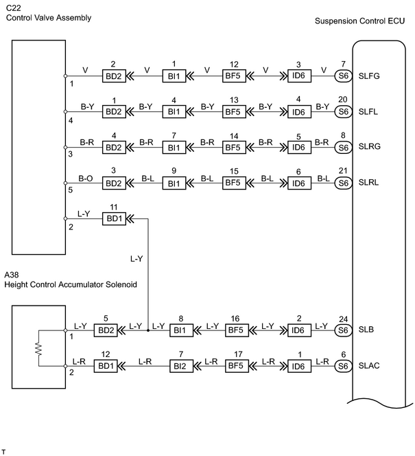
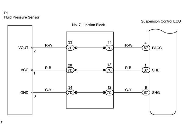
INSPECTION PROCEDURE
PROCEDURE
|
1. |
INSPECT CONTROL VALVE SOLENOID AND HEIGHT CONTROL ACCUMULATOR SOLENOID |
|
(a) Disconnect the control valve solenoid connector. |
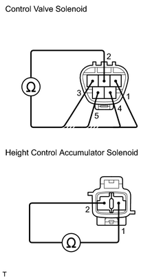
|
(b) Measure the resistance between terminals 2 and 1, 3, 4, 5 of the control valve connector.
Standard resistance:
|
Tester Connection |
Specified Condition |
|---|---|
|
1 - 2 |
Below 1 Ω |
|
2 - 3 |
Below 1 Ω |
|
2 - 4 |
Below 1 Ω |
|
2 - 5 |
Below 1 Ω |
(c) Disconnect the accumulator solenoid connector from the height control accumulator.
(d) Measure the resistance between terminals 1 and 2 of the accumulator solenoid connector.
Standard resistance:
|
Tester Connection |
Specified Condition |
|---|---|
|
1 - 2 |
Below 1 Ω |
| NG |

|
REPLACE CONTROL VALVE ASSEMBLY OR HEIGHT CONTROL ACCUMULATOR SOLENOID |
|

|
2. |
CHECK WIRE HARNESS (SUSPENSION CONTROL ECU - CONTROL VALVE ASSEMBLY AND HEIGHT CONTROL ACCUMULATOR AND FLUID PRESSURE SENSOR) |
| NG |
|
|
|
3. |
CHECK FLUID PRESSURE SENSOR |
|
(a) Start the engine and push the vehicle height select switch to select the "N" mode. (b) Measure the voltage between terminals 2 and 3 of the fluid pressure sensor connector. Standard voltage:
|
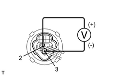
|
| NG |
|
| OK |
|

|

|