| Last Modified: 7-3-2017 | 6.8:8.0.40 | Doc ID: RM000001D6V01JX |
| Model Year Start: 2007 | Model: LX470 | Prod Date Range: [08/2006 - ] |
| Title: 2UZ-FE ENGINE CONTROL SYSTEM: SFI SYSTEM: VC Output Circuit; 2007 MY LX470 [08/2006 - ] | ||
|
VC Output Circuit |
DESCRIPTION
The ECM constantly generates 5 V power from the battery voltage supplied to the +B (BATT) terminal to operate the microprocessor. The ECM also provides this power to the sensors through the VC output circuit.
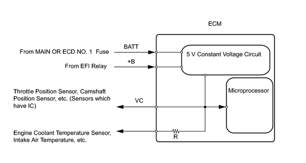
When the VC circuit is short-circuited, the microprocessor in the ECM and sensors that are supplied power through the VC circuit are deactivated because the power is not supplied from the VC circuit. Under this condition, the system does not start up and the MIL does not illuminate even if the system malfunctions.
HINT:
Under normal conditions, the MIL is illuminated for several seconds when the ignition switch is first turned ON. The MIL goes off when the engine is started.
WIRING DIAGRAM
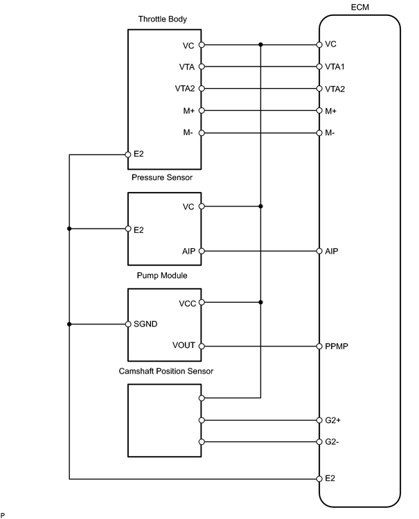
INSPECTION PROCEDURE
PROCEDURE
|
1. |
CHECK MIL |
(a) Check that the Malfunction Indicator Lamp (MIL) lights up when turning the ignition switch ON.
OK:
MIL lights up
| OK |

|
|

|
2. |
CHECK CONNECTION BETWEEN INTELLIGENT TESTER AND ECM |
(a) Connect the intelligent tester to the CAN VIM. Then connect the CAN VIM to the DLC3.
(b) Turn the ignition switch ON and intelligent tester ON.
(c) Check the communication between the intelligent tester and ECM.
Result
|
Communication is possible |
A |
|
Communication is not possible |
B |
| A |
|
|
|
3. |
INSPECT ECM |
(a) Turn the ignition switch ON.
|
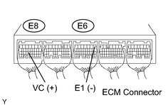
(b) Measure the voltage of the ECM connector. Result: Voltage is not 5 V |
|
|
|
4. |
CHECK MIL (THROTTLE POSITION SENSOR) |
(a) Disconnect the T24 throttle body connector.
(b) Turn the ignition switch ON.
(c) Check the MIL.
Result
|
MIL illuminates |
A |
|
MIL does not illuminate |
B |
| A |
|
|
|
5. |
CHECK MIL (CAMSHAFT POSITION SENSOR) |
(a) Disconnect the C39 camshaft position sensor connector.
(b) Turn the ignition switch ON.
(c) Check the MIL.
Result
|
MIL illuminates |
A |
|
MIL does not illuminate |
B |
| A |
|
|
|
6. |
CHECK MIL (CANISTER PUMP MODULE) |
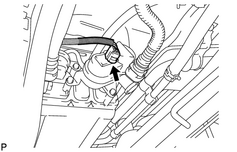
(a) Remove the spare tire.
|
(b) Disconnect the L4 canister pump module connector. |
|
(c) Turn the ignition switch ON.
(d) Check the MIL.
Result
|
MIL illuminates |
A |
|
MIL does not illuminate |
B |
| A |
|
|
|
7. |
CHECK MIL (PRESSURE SENSOR) |
(a)
Remove the intake manifold
![2007 MY LX470 [08/2006 - ]; 2UZ-FE ENGINE MECHANICAL: CYLINDER HEAD: REMOVAL+](../../../../stylegraphics/info.gif "2007 MY LX470 [08/2006 - ]; 2UZ-FE ENGINE MECHANICAL: CYLINDER HEAD: REMOVAL+") .
.
(b) Disconnect the A57 pressure sensor.
(c) Turn the ignition switch ON.
(d) Check the MIL.
Result
|
MIL illuminates |
A |
|
MIL does not illuminate |
B |
| A |
|
|
|
8. |
CHECK HARNESS AND CONNECTOR |
(a) Disconnect the T24 throttle body connector.
(b) Disconnect the C39 camshaft position sensor connector.
(c) Disconnect the L4 canister pump module connector.
(d) Disconnect the A57 pressure sensor.
|
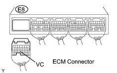
(e) Disconnect the E8 ECM connector. |
|
(f) Measure the resistance of the wire harness side connector.
Standard resistance (check for short):
|
Tester Connection |
Specified Condition |
|---|---|
|
E8-23 (VC) - Body ground |
10 kΩ or higher |
| NG |
|
| OK |
|

|

|