- Mayday ECU assembly
- Map light plate assembly
- Mayday switch assembly
- Wire harness
| Last Modified: 7-3-2017 | 6.8:8.0.40 | Doc ID: RM000001EG5004X |
| Model Year Start: 2007 | Model: LX470 | Prod Date Range: [08/2006 - ] |
| Title: CELLULAR COMMUNICATION: LEXUS LINK SYSTEM: 4-7; EMERGENCY, VOL+ or VOL- Button has Connection Error; 2007 MY LX470 [08/2006 - ] | ||
|
DTC |
4-7 |
EMERGENCY, VOL+ or VOL- Button has Connection Error |
DESCRIPTION
This DTC is output when one of the following occurs: 1) the mayday ECU assembly is malfunctioning; 2) the mayday switch assembly is malfunctioning; or 3) the wire harness between the mayday ECU assembly and the map light plate assembly is open or short.
|
DTC No. |
DTC Detection Condition |
Trouble Area |
|---|---|---|
|
4 - 7 |
Communication or communication line is abnormal between mayday ECU and map light plate (mayday switch) |
|
WIRING DIAGRAM
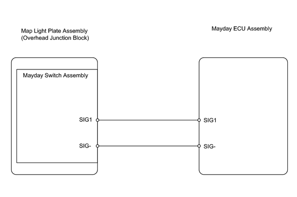
INSPECTION PROCEDURE
PROCEDURE
|
1. |
CHECK WIRE HARNESS (ECU - MAP LIGHT PLATE ASSEMBLY (MAYDAY SWITCH ASSEMBLY)) |
|
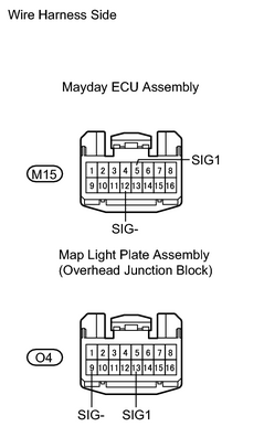
(a) Disconnect the M15 ECU connector. (b) Disconnect the O4 map light plate connector. (c) Measure the resistance of the wire harness side connectors. Standard resistance:
|
|
| NG |

|
REPAIR OR REPLACE HARNESS AND CONNECTOR THEN CLEAR HISTORIC DTC |
|

|
2. |
INSPECT MAYDAY SWITCH ASSEMBLY |
|
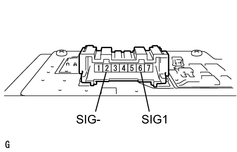
(a) Remove the map light plate assembly. (b) Remove the mayday switch assembly from the map light plate assembly. (c) Measure the resistance of the switch when each switch is pressed. Standard resistance:
|
|
| NG |
|
|
|
3. |
INSPECT MAP LIGHT PLATE ASSEMBLY |
|
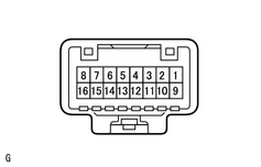
(a) Install the mayday switch assembly to the map light plate assembly. (b) Measure the resistance of the switch when each switch is pressed. Standard resistance:
|
|
| NG |
|
| OK |
|
REPLACE MAYDAY ECU ASSEMBLY TOGETHER WITH MAYDAY BATTERY AND THEN PERFORM REGISTRATION |

|

|