- VGRS actuator
- VGRS ECU
| Last Modified: 7-3-2017 | 6.8:8.0.40 | Doc ID: RM000001F6B001X |
| Model Year Start: 2007 | Model: LX470 | Prod Date Range: [08/2006 - ] |
| Title: STEERING COLUMN: VARIABLE GEAR RATIO STEERING SYSTEM: C1561/61; Lock Mechanism Malfunction; 2007 MY LX470 [08/2006 - ] | ||
|
DTC |
C1561/61 |
Lock Mechanism Malfunction |
DESCRIPTION
When the VGRS ECU detects a malfunction in the lock mechanism, it turns the warning light on, records the DTC, and stops VGRS operation.
|
DTC No. |
DTC Detection Condition |
Trouble Area |
|---|---|---|
|
C1561 / 61 |
The system detects that the LG terminal voltage is equal to battery voltage x 0.4 +- 3 V, or that the LG terminal voltage is outside the range of battery voltage x 0.6 +- 3 V for 1.2 sec. |
|
WIRING DIAGRAM
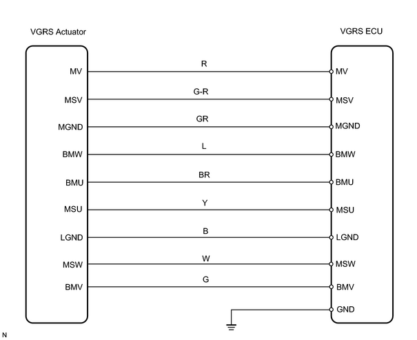
INSPECTION PROCEDURE
PROCEDURE
|
1. |
CHECK POSITION OF VGRS ECU CONNECTORS |
(a) Check that VGRS ECU connectors are properly connected to the ECU.
OK:
Connection is normal
| NG |

|
DTC C1561/61 IS DETECTED BECAUSE CONNECTOR IS DISCONNECTED OR IS LIKELY TO BE DISCONNECTED. CONNECT CONNECTOR CORRECTLY |
|

|
2. |
CHECK WIRE HARNESS |
|
(a) Turn the ignition switch OFF. |
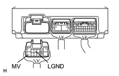
|
(b) Disconnect the V13 VGRS ECU connector.
(c) Measure the resistance between terminals V13-10 (MV) and V13-3 (LGND) of the VGRS ECU connector.
Standard resistance:
1 to 100 Ω
(d) Check the continuity between terminals V13-10 (MV) and V13-3 (LGND) of the VGRS ECU and body ground.
OK:
Continuity
| NG |
|
| OK |
|

|

|