- Occupant classification ECU receives line short circuit signal, open circuit signal, short circuit to ground signal or short circuit to B+ signal in pressure sensor circuit for 2 seconds.
- Occupant classification sensor malfunction
- Occupant classification ECU malfunction
| Last Modified: 7-3-2017 | 6.8:8.0.40 | Doc ID: RM000001PK6009X |
| Model Year Start: 2007 | Model: LX470 | Prod Date Range: [08/2006 - ] |
| Title: SUPPLEMENTAL RESTRAINT SYSTEM: OCCUPANT CLASSIFICATION SYSTEM: B1774,B1775; Pressure Sensor Circuit Malfunction; 2007 MY LX470 [08/2006 - ] | ||
|
DTC |
B1774 |
Pressure Sensor Circuit Malfunction |
|
DTC |
B1775 |
Pressure Sensor Power Source Circuit Malfunction |
DESCRIPTION
The pressure sensor circuit consists of the occupant classification ECU and the occupant classification sensor.
The occupant classification sensor sends the pressure signal to the occupant classification ECU to control the occupant classification system.
DTCs B1774 and B1775 are recorded when a malfunction is detected in the pressure sensor circuit.
|
DTC No. |
DTC Detection Condition |
Trouble Area |
|---|---|---|
|
B1774 B1775 |
When one of following conditions is met: |
|
NOTICE:
Replace the occupant classification ECU, occupant classification sensor, seat cushion cover pad, seat cushion cover and seat cushion seat heater as a 5 part set (see supply set part no.).
HINT:
- When DTC B1650/32 is detected as a result of troubleshooting the supplemental restraint system, check the DTCs stored in the occupant classification ECU, and perform troubleshooting for those DTCs first.
- Use the intelligent tester to check for DTCs of the occupant classification ECU, otherwise the DTC cannot be read.
WIRING DIAGRAM
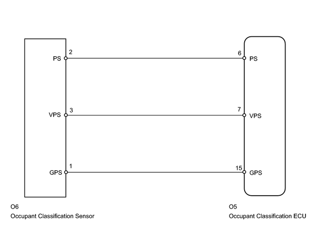
INSPECTION PROCEDURE
HINT:
- If troubleshooting (wire harness inspection) is difficult to perform, remove the passenger seat installation bolts to see the undersurface of the seat cushion.
- In the above case, hold the seat so that it does not tip over. Holding the seat up for a long period of time may cause problems, such as seat rail deformation. Hold the seat up only for as long as necessary.
- After performing the zero point calibration, check for DTCs to confirm that the calibration is completed normally. (If it fails, DTC B1797 will be output.)
PROCEDURE
|
1. |
CHECK FOR DTC |
(a) Turn the ignition switch ON.
(b)
Clear the DTCs stored in the memory
![2007 MY LX470 [08/2006 - ]; SUPPLEMENTAL RESTRAINT SYSTEM: OCCUPANT CLASSIFICATION SYSTEM: DTC CHECK / CLEAR](../../../../stylegraphics/info.gif "2007 MY LX470 [08/2006 - ]; SUPPLEMENTAL RESTRAINT SYSTEM: OCCUPANT CLASSIFICATION SYSTEM: DTC CHECK / CLEAR") .
.
HINT:
First clear DTCs stored in the occupant classification ECU and then in the center airbag sensor.
(c) Turn the ignition switch OFF.
(d) Turn the ignition switch ON.
(e)
Check the DTCs
.
OK:
DTCs B1774 and B1775 are not output.
HINT:
DTCs other than B1774 and B1775 may be output at this time, but they are not related to this check.
| OK |

|
|

|
2. |
CHECK CONNECTOR |
(a) Turn the ignition switch OFF.
(b) Disconnect the cable from the negative (-) battery terminal, and wait for at least 90 seconds.
(c) Check that the connectors are properly connected to the occupant classification ECU and the occupant classification sensor.
OK:
The connectors are properly connected.
(d) Disconnect the connectors from the occupant classification ECU and the occupant classification sensor.
(e) Check that the terminals of the connectors are not damaged.
OK:
The terminals are not deformed or damaged.
HINT:
If the connectors are not connected securely, reconnect the connectors and proceed to the next inspection.
| NG |
|
|
|
3. |
CHECK NO. 1 SEAT WIRE (TO B+) |
|
(a) Disconnect the connector from the occupant classification ECU and occupant classification sensor. |
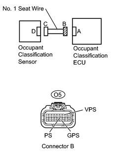
|
(b) Connect the cable to the negative (-) battery terminal.
(c) Turn the ignition switch ON.
(d) Measure the voltage of the wire harness side connector.
Standard voltage:
|
Tester Connection |
Specified Condition |
|---|---|
|
O5-6 (PS) - Body ground |
Below 1 V |
|
O5-7 (VPS) - Body ground |
Below 1 V |
|
O5-15 (GPS) - Body ground |
Below 1 V |
| NG |
|
|
|
4. |
CHECK NO. 1 SEAT WIRE (FOR OPEN) |
|
(a) Turn the ignition switch OFF. |
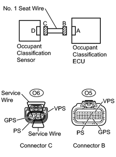
|
(b) Disconnect the cable from the negative (-) battery terminal, and wait for at least 90 seconds.
(c) Using a service wire, connect terminals O6-2 (PS) and O6-3 (VPS), and connect terminals O6-3 (VPS) and O6-1 (GPS) of connector C.
NOTICE:
Do not forcibly insert the service wire into the terminals of the connector when connecting.
(d) Measure the resistance of the wire harness side connector.
Standard resistance:
|
Tester Connection |
Specified Condition |
|---|---|
|
O5-6 (PS) - O5-7 (VPS) |
Below 1 Ω |
|
O5-7 (VPS) - O5-15 (GPS) |
Below 1 Ω |
| NG |
|
|
|
5. |
CHECK NO. 1 SEAT WIRE (TO GROUND) |
|
(a) Disconnect the service wire from connector C. |
|
(b) Measure the resistance of the wire harness side connector.
Standard resistance:
|
Tester Connection |
Specified Condition |
|---|---|
|
O5-6 (PS) - Body ground |
1 MΩ or higher |
|
O5-7 (VPS) - Body ground |
1 MΩ or higher |
|
O5-15 (GPS) - Body ground |
1 MΩ or higher |
| NG |
|
|
|
6. |
CHECK NO. 1 SEAT WIRE (FOR SHORT) |
|
(a) Measure the resistance of the wire harness side connector. Standard resistance:
|
|
| NG |
|
|
|
7. |
CHECK FOR DTC |
(a) Connect the connectors to the occupant classification ECU and the occupant classification sensor.
(b) Connect the cable to the negative (-) battery terminal.
(c) Turn the ignition switch ON.
(d)
Clear the DTCs stored in the memory
.
HINT:
First clear DTCs stored in the occupant classification ECU and then in the center airbag sensor.
(e) Turn the ignition switch OFF.
(f) Turn the ignition switch ON.
(g)
Check the DTCs
.
OK:
DTCs B1774 and B1775 are not output.
HINT:
DTCs other than B1774 and B1775 may be output at this time, but they are not related to this check.
| OK |
|
|
|
8. |
REPLACE FRONT SEAT CUSHION (OCCUPANT CLASSIFICATION SENSOR) |
(a) Turn the ignition switch OFF.
(b) Disconnect the cable from the negative (-) battery terminal, and wait for at least 90 seconds.
(c)
Replace the front seat cushion (with occupant classification ECU and occupant classification sensor)
.
HINT:
Perform the inspection using parts from a normal vehicle if possible.
(d) Connect the cable to the negative (-) battery terminal.
(e) Turn the ignition switch ON.
(f)
Clear the DTCs stored in the memory
.
HINT:
First clear DTCs stored in the occupant classification ECU and then in the center airbag sensor.
(g) Turn the ignition switch OFF.
(h) Turn the ignition switch ON.
(i)
Check the DTCs
.
OK:
DTCs B1774 and B1775 are not output.
HINT:
DTCs other than B1774 and B1775 may be output at this time, but they are not related to this check.
|
|
9. |
PERFORM ZERO POINT CALIBRATION |
(a) Connect the intelligent tester (with CAN VIM) to the DLC3.
(b) Turn the ignition switch ON.
(c)
Using the intelligent tester, perform the zero point calibration
.
(d) Turn the ignition switch OFF.
(e) Turn the ignition switch ON.
(f)
Clear the DTCs stored in the memory
.
HINT:
If DTCs are not cleared at this time, past DTCs will remain.
|
|
10. |
CHECK FOR DTC |
HINT:
Check that the zero point calibration is completed normally. If either of the following occurs, DTC B1797 will be output (Refer to INITIALIZATION
):
- Zero point calibration is performed when the conditions for the calibration are not satisfied.
- Zero point calibration has failed.
(a) Turn the ignition switch ON.
(b)
Clear the DTCs stored in the memory
.
HINT:
First clear DTCs stored in the occupant classification ECU and then in the center airbag sensor.
(c) Turn the ignition switch OFF.
(d) Turn the ignition switch ON.
(e)
Check the DTCs
.
OK:
DTC B1797 is not output.
| NG |
|
|
|
11. |
PERFORM SENSITIVITY CHECK |
(a)
Perform the sensitivity check
.
| NEXT |
|

|

|