|
How to use this manual
- Contents of the Manual
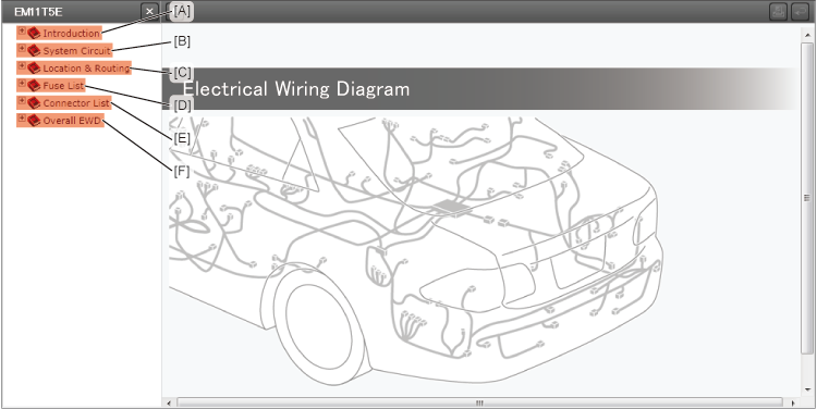
- The manual consists of the following sections.
- [A]: Introduction
-
- Indicates the contents of this manual, provides instructions on how to use the manual, and defines the abbreviations and symbols used in this manual.
- [B]: System Circuit
-
- Indicates the power source and ground point circuits, and the circuit diagrams for each system.
(Only the wiring information for complete circuits is included.)
- [C]: Location & Routing
-
- Indicates where the wire harnesses, connectors and ground points are located in each vehicle section such as the engine compartment and instrument panel. Also indicates the locations of the relays, relay blocks (R/B), antennas, ECU, etc. along with the inner circuits as the relay locations in each vehicle section.
- [D]: Fuse List
-
- Provides the list of each of the power source (fuse and fusible link) locations and the related system data for each vehicle section.
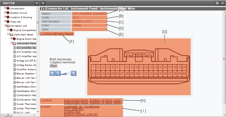
- [E]: Connector List
-
- Provides the detailed information (shape, repair information, part No., etc.) on each connector and ground point for each wire harness. Also indicates the related systems and references the "Location and Routing".
- System Circuit
- Electrical circuits of each system are shown from the fuses to the ground points for each function. The power source circuits are shown from the vehicle power source (batteries) to the fuses, and the ground point circuits are shown from the ground points to the parts.
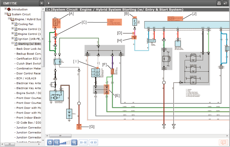
- [A]: Fuse
-
- Indicates the name and capacity of the fuse.
-
-
- HINT:
- Refer to the "Location & Routing".
- [B]: Power Source System Identification
-
- Indicates the ignition key position(s) when the power is supplied to the fuse(s).
- [C]: Specification Identification
-
- ( ) is used to indicate different connector, wiring, wiring color, etc. when the vehicle model, engine type, specification, etc., are different.
-
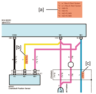
- How to see the differences
-
-
-
-
-
-
| See [a] |
*3:1NR-FE |
|
*4:1NZ-FE |
| |
*1:w/ Stop & Start System
|
| Indication: |
1NR-FE |
or |
1NZ-FE |
and |
w/ Stop & Start System |
|
|
|
|
|
|
|
*3 |
|
*4 |
|
*1 |
-
-
-
-
-
-
| See [a] |
*4:1NZ-FE |
|
*2:w/o Stop & Start System
|
| Indication: |
1NZ-FE |
or |
w/o Stop & Start System |
|
|
|
|
|
*4 |
|
*2 |
- [D]: Wire Color
-
- Indicates the wiring color. Wire colors are indicated by an alphabetical code.
-
- Colored wiring (general wiring)
-
-
- For example, "L-Y" indicates that the basic color of the wiring is blue, with a yellow stripe.
-
-
- Example: L-Y
-
-
- Copper wires
| B=Black |
W=White |
BR=Brown |
| L=Blue |
V=Violet |
SB=Sky Blue |
| R=Red |
G=Green |
LG=Light Green |
| P=Pink |
Y=Yellow |
GR=Gray |
| O=Orange |
BE=Beige |
DG=Dark Gray |
-
-
- Aluminum wires
-
-
- NOTICE:
- Do not splice into aluminum wires for power sources or signals.
-
-
-
- The painted wiring is white and has stripes with a wiring color near the terminal.
| Code |
Wiring Color |
Painted Wiring |
| B |
Black |
 |
| R |
Red |
 |
| G |
Green |
 |
| L |
Blue |
 |
| BR |
Brown |
 |
| Y |
Yellow |
 |
| V |
Violet |
 |
| W-B |
White/Black |
 |
| P |
Pink |
 |
| LG |
Light Green |
 |
| SB |
Sky Blue |
 |
|
 |
| *1 |
Connector |
| *2 |
Wiring color |
| *3 |
White wiring |
|
|
- [E]: Junction Block Connector Code
-
- Indicates the codes for the connectors connected to the Junction Blocks.
-
-
- HINT:
- Refer to the "Location & Routing" for the shape.
-
-
| Junction Block Connector |
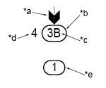 |
| *a |
Represents the inner circuits of the Junction Blocks. |
| *b |
Indicates the Junction Block code/number. |
| *c |
Indicates the sequence number of the connector which belongs to the Junction Block. |
| *d |
Indicates the terminal number. |
| *e |
If there is only a number inside, it indicates that this is a relay block, fuse block or other. |
|
- [F]: Switch
-
- A single switch is indicated normally open.
-
-
- HINT:
- Refer to the relevant Repair Manual for the operations and operating conditions of the switches.
- [G]: Ground Point Code
-
- Indicates the ground point.
-
-
- HINT:
- Refer to "Location and Routing" for the locations.
-
-
| Ground point code |
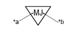 |
| *a |
Indicates the wire harness which is connected to the ground point. |
| *b |
An alphabetical code is used to distinguish the ground point.
For example, "MJ" indicates that wire "M" is connected to point "J". |
|
- [H]: Wire and Wire Connector Code
-
- Indicates the code for the connectors which are used to join two wire harnesses.
-
-
- HINT:
- Refer to "Connector List" for the shape of the connector.
-
-
| Wire and Wire Connector |
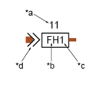 |
| *a |
Indicates the terminal number. |
| *b |
Indicates the wire harnesses which are connected.
For example, "FH" indicates that the connecter joins "F", the female connector*1, and "H", the male connector*2, of the two wire harnesses.
*1 Female connector: female terminal
*2 Male connector: male terminal |
| *c |
Indicates the sequential number of the connector used for the same combination of the wire harnesses. |
| *d |
Indicates that this is a male connector. |
|
- [I]: Terminal No.
-
- Indicates the terminal number of the connector which is connected.
- [J]: Part Name and Connector Code
-
- Indicates the part name and the code for the connector which is connected to the part.
-
-
- HINT:
- Refer to the "Connector List" for the shape of the connector.
-
-
| Part connector |
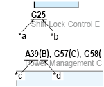 |
| *a |
Indicates the wire harness to which the connector belongs.
For example, "G" indicates that the connector is used on wire "G".
Refer to the "Location & Routing" for the wire harness name of wire "G". |
| *b |
Indicates the sequential number of the connector which belongs to the wire harness. |
| *c |
Connector code |
| *d |
Distinguishes the connector when there are multiple number of connectors connected to the part or when there are multiple types of connectors for different specifications. |
|
-
- The information in this manual is about the wire harnesses. Information about component and assembly parts is for reference, but in some cases this reference information might not be included or might differ from the actual vehicle.
When inspecting or repairing a vehicle, refer to the relevant Repair Manual.
|
Example:Front right door |
 |
| *1 |
Wire harness |
| *2 |
Component parts |
| *a |
When inspecting or repairing, refer to the Repair Manual. |
| *b |
Assembly parts |
|
Location & Routing
- Indicates where the wire harnesses, connectors and ground points are located in each vehicle section such as the engine compartment and instrument panel. Also indicates the locations of the relays, relay blocks (R/B), antennas, ECU, etc. along with the inner circuits as the relay locations in each vehicle section.
-
-
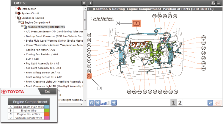
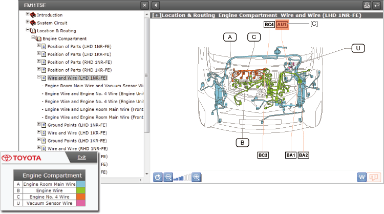
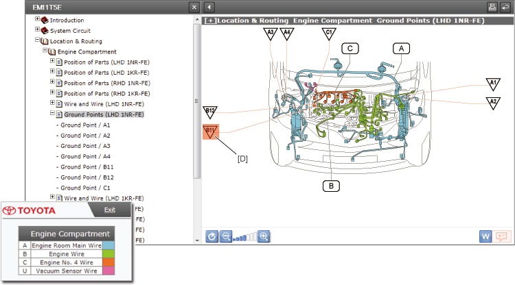
- Indicates where the wire harness and connecters are located for each vehicle section. Also indicates the ground point and each connector code.
- (The connector code is the same as the code used in the "System Circuit".)
- [A]: Wire Harness Code
-
- Each wire harness is represented by a code. Wire harness codes are used in the parts codes, connector codes, wire and wire connector codes, and ground point codes as the initial character.
- [B]: Part Connector Code
-
- Indicates the code for the connector which is connected to the part.
- [C]: Wire and Wire Connector Code
-
- Indicates the code for the connectors which are used to join two wire harnesses.
- [D]: Ground Point Code
-
- Indicates the ground point.
-
-
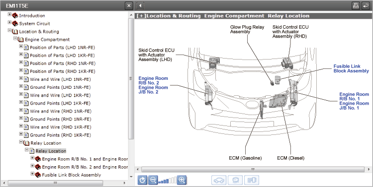
- Indicates where a relay, Relay Block (R/B), Junction Block (J/B), Fusible Link (F/L), ECU, and others are located.
-
| c. |
Junction Block (J/B) / Relay Block (R/B) / Inner Circuit |
-
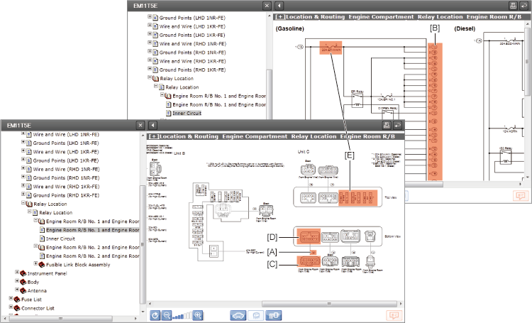
- Indicates the connectors, relays, and fuses which are connected to the Junction Blocks (J/B) and others. Also indicates the inner circuits.
- [A]: Connector No.
-
- Indicates the number for the connector which is connected to the Junction Block.
- [B]: Connector No. and Terminal No.
-
- Indicates the number for the connector which is connected to the Junction Block, and also the terminal number.
- [C]: Connector Shape and Terminal No.
-
- Indicates the shape of the connector on the wire harness side.
- The number indicates the terminal number.
- [D]: Connector Shape and Terminal No.
-
- Indicates the shape of the connector on the Junction Block side.
- The number indicates the terminal number.
- [E]: Fuse
-
- Indicates the name and capacity of the fuse.
- Fuse List
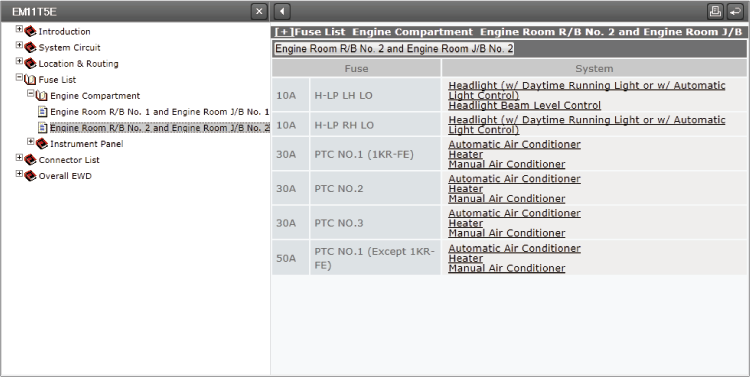
- Provides the list of each of the power source (fuse and fusible link) locations and the related system data for each vehicle section.
- Connector List
- [A]: Name
-
- Indicates the name of the part where the connector is connected.
- [B]: Code
-
- Indicates the connector code.
- (The code is the same as the code used in the "System Circuit" and "Location & Routing".)
- [C]: Part No.
-
- Indicates the Toyota Part No. of the connector.
- [D]: Color
-
- Indicates the color of the connector.
- [E]: Spec
-
- Indicates when the vehicle model, engine type, or specification is different.
- [F]: Wire Harness Repair
-
- Indicates the information on the wire harness repair.
- [G]: Connector Shape and Terminal No.
-
- Indicates the shape of the connector on the wire harness side.
- The terminal numbers are the same as the terminal numbers used in the "System Circuit".
- [H]: Location
-
- Refers the "Location and Routing" for the connectors.
- [I]: System
-
- Indicates the related system for the terminal number.
|