| Last Modified: 11-27-2007 | 1.6 G | |
| Service Category: Drivetrain | Section: Automatic Transmission/Transaxle | |
| Model Year: 2008 | Model: LX570 | Doc ID: RM000000ODH01JX |
| Title: AB60F AUTOMATIC TRANSMISSION / TRANSAXLE: VALVE BODY ASSEMBLY: INSPECTION (2008 LX570) | ||
INSPECTION
1. INSPECT SHIFT SOLENOID VALVE SL1
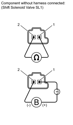
(a) Measure the resistance according to the value(s) in the table below.
Standard Resistance:
|
Tester Connection |
Condition |
Specified Condition |
|---|---|---|
|
1 - 2 |
20°C (68°F) |
5.0 to 5.6 Ω |
(b) Apply 12 V battery voltage to the shift solenoid valve and check that the valve moves and makes an operating noise.
OK:
|
Measurement Condition |
Specified Condition |
|---|---|
|
Battery positive (+) with a 21 W bulb → Terminal 1 Battery negative (-) → Terminal 2 |
Valve moves and makes an operating noise |
If the result is not as specified, replace the solenoid valve.
2. INSPECT SHIFT SOLENOID VALVE S1
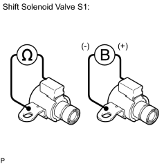
(a) Measure the resistance according to the value(s) in the table below.
Standard Resistance:
|
Tester Connection |
Condition |
Specified Condition |
|---|---|---|
|
Shift solenoid valve S1 connector terminal - Shift solenoid valve S1 body |
20°C (68°F) |
11 to 15 Ω |
(b) Apply 12 V battery voltage to the shift solenoid valve and check that the valve moves and makes an operating noise.
OK:
|
Measurement Condition |
Specified Condition |
|---|---|
|
Battery positive (+) → Shift solenoid valve S1 connector Battery negative (-) → Shift solenoid valve S1 body |
Valve moves and makes an operating noise |
If the result is not as specified, replace the solenoid valve.
3. INSPECT SHIFT SOLENOID VALVE S2
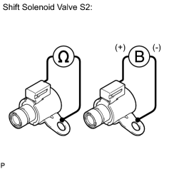
(a) Measure the resistance according to the value(s) in the table below.
Standard Resistance:
|
Tester Connection |
Condition |
Specified Condition |
|---|---|---|
|
Shift solenoid valve S2 connector terminal - Shift solenoid valve S2 body |
20°C (68°F) |
11 to 15 Ω |
(b) Apply 12 V battery voltage to the shift solenoid valve and check that the valve moves and makes an operating noise.
OK:
|
Measurement Condition |
Specified Condition |
|---|---|
|
Battery positive (+) → Shift solenoid valve S2 connector Battery negative (-) → Shift solenoid valve S2 body |
Valve moves and makes an operating noise |
If the result is not as specified, replace the solenoid valve.
4. INSPECT SHIFT SOLENOID VALVE S3
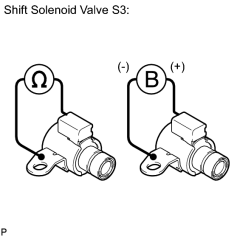
(a) Measure the resistance according to the value(s) in the table below.
Standard Resistance:
|
Tester Connection |
Condition |
Specified Condition |
|---|---|---|
|
Shift solenoid valve S3 connector terminal - Shift solenoid valve S3 body |
20°C (68°F) |
11 to 15 Ω |
(b) Apply 12 V battery voltage to the shift solenoid valve and check that the valve moves and makes an operating noise.
OK:
|
Measurement Condition |
Specified Condition |
|---|---|
|
Battery positive (+) → Shift solenoid valve S3 connector Battery negative (-) → Shift solenoid valve S3 body |
Valve moves and makes an operating noise |
If the result is not as specified, replace the solenoid valve.
5. INSPECT SHIFT SOLENOID VALVE S4
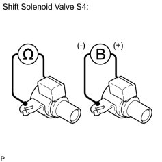
(a) Measure the resistance according to the value(s) in the table below.
Standard Resistance:
|
Tester Connection |
Condition |
Specified Condition |
|---|---|---|
|
Shift solenoid valve S4 connector terminal - Shift solenoid valve S4 body |
20°C (68°F) |
11 to 15 Ω |
(b) Apply 12 V battery voltage to the shift solenoid valve and check that the valve moves and makes an operating noise.
OK:
|
Measurement Condition |
Specified Condition |
|---|---|
|
Battery positive (+) → Shift solenoid valve S4 connector Battery negative (-) → Shift solenoid valve S4 body |
Valve moves and makes an operating noise |
If the result is not as specified, replace the solenoid valve.
6. INSPECT SHIFT SOLENOID VALVE SL2
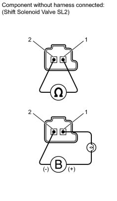
(a) Measure the resistance according to the value(s) in the table below.
Standard Resistance:
|
Tester Connection |
Condition |
Specified Condition |
|---|---|---|
|
1 - 2 |
20°C (68°F) |
5.0 to 5.6 Ω |
(b) Apply 12 V battery voltage to the shift solenoid valve and check that the valve moves and makes an operating noise.
OK:
|
Measurement Condition |
Specified Condition |
|---|---|
|
Battery positive (+) with a 21 W bulb → Terminal 1 Battery negative (-) → Terminal 2 |
Valve moves and makes an operating noise |
If the result is not as specified, replace the solenoid valve.
7. INSPECT SHIFT SOLENOID VALVE SR
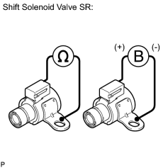
(a) Measure the resistance according to the value(s) in the table below.
Standard Resistance:
|
Tester Connection |
Condition |
Specified Condition |
|---|---|---|
|
Shift solenoid valve SR connector terminal - Shift solenoid valve SR body |
20°C (68°F) |
11 to 15 Ω |
(b) Apply 12 V battery voltage to the shift solenoid valve and check that the valve moves and makes an operating noise.
OK:
|
Measurement Condition |
Specified Condition |
|---|---|
|
Battery positive (+) → Shift solenoid valve SR connector Battery negative (-) → Shift solenoid valve SR body |
Valve moves and makes an operating noise |
If the result is not as specified, replace the solenoid valve.
8. INSPECT SHIFT SOLENOID VALVE SLT
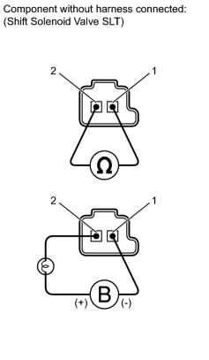
(a) Measure the resistance according to the value(s) in the table below.
Standard Resistance:
|
Tester Connection |
Condition |
Specified Condition |
|---|---|---|
|
1 - 2 |
20°C (68°F) |
5.0 to 5.6 Ω |
(b) Apply 12 V battery voltage to the shift solenoid valve and check that the valve moves and makes an operating noise.
OK:
|
Measurement Condition |
Specified Condition |
|---|---|
|
Battery positive (+) with a 21 W bulb → Terminal 2 Battery negative (-) → Terminal 1 |
Valve moves and makes an operating noise |
If the result is not as specified, replace the solenoid valve.
9. INSPECT SHIFT SOLENOID VALVE SLU
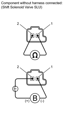
(a) Measure the resistance according to the value(s) in the table below.
Standard Resistance:
|
Tester Connection |
Condition |
Specified Condition |
|---|---|---|
|
1 - 2 |
20°C (68°F) |
5.0 to 5.6 Ω |
(b) Apply 12 V battery voltage to the shift solenoid valve and check that the valve moves and makes an operating noise.
OK:
|
Measurement Condition |
Specified Condition |
|---|---|
|
Battery positive (+) with a 21 W bulb → Terminal 2 Battery negative (-) → Terminal 1 |
Valve moves and makes an operating noise |
If the result is not as specified, replace the solenoid valve.

|

|