- The mass air flow meter power source circuit is open or shorted.
| Last Modified: 11-27-2007 | 1.6 D | |
| Service Category: Engine/Hybrid System | Section: Engine Control | |
| Model Year: 2008 | Model: LX570 | Doc ID: RM000000PDS068X |
| Title: 3UR-FE ENGINE CONTROL: SFI SYSTEM: FREEZE FRAME DATA (2008 LX570) | ||
FREEZE FRAME DATA
1. DESCRIPTION
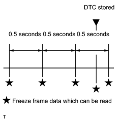
Freeze frame data records the engine conditions (fuel system, calculated load, engine coolant temperature, fuel trim, engine speed, vehicle speed, etc.) when a malfunction is detected. When troubleshooting, it can help determine if the vehicle was running or stopped, the engine was warmed up or not, the air-fuel ratio was Lean or Rich, and other data from the time the malfunction occurred.
HINT:
If it is impossible to duplicate the problem even though a DTC is output, confirm the freeze frame data.
The ECM records engine conditions in the form of freeze frame data every 0.5 seconds. Using the Techstream, 5 separate sets of freeze frame data can be checked.
2. LIST OF FREEZE FRAME DATA
|
Display Item |
Measurement Item |
Diagnostic Note |
|---|---|---|
|
Injector (Port) |
Injection period of No. 1 cylinder |
- |
|
IGN Advance |
Ignition advance |
- |
|
Calculate Load |
Calculated load |
Calculated load by the ECM. |
|
Vehicle Load |
Vehicle load |
- |
|
MAF |
Mass air flow volume |
If the mass air flow volume is approximately 0.0 g/sec.:
If the mass air flow volume is 160.0 g/sec. or more:
|
|
Engine Speed |
Engine speed |
- |
|
Vehicle Speed |
Vehicle speed |
Speed indicated on the speedometer. |
|
Coolant Temp |
Engine coolant temperature |
If the value is -40°C (-40°F), the sensor circuit is open. If the value is 140°C (284°F) or higher, the sensor circuit is shorted. |
|
Intake Air |
Intake air temperature |
If the value is -40°C (-40°F), the sensor circuit is open. If the value is 140°C (284°F) or higher, the sensor circuit is shorted. |
|
2nd Air System Status |
Second air system status |
- |
|
Air-Fuel Ratio |
Ratio compared to stoichiometric level |
- |
|
Purge Density Learn Value |
Learning value of purge density |
- |
|
Evap Purge Flow |
Ratio of evaporative purge flow to intake air volume |
- |
|
EVAP (Purge) VSV |
EVAP purge VSV duty ratio |
- |
|
Knock Correct Learn Value |
Correction learning value of knocking |
- |
|
Knock Feedback Value |
Feedback value of knocking |
- |
|
Accelerator Position No. 1 |
Absolute Accelerator Pedal Position (APP) No. 1 |
- |
|
Accelerator Position No. 2 |
Absolute APP No. 2 |
- |
|
Throttle Pos. Sensor Output |
Throttle position |
- |
|
Throttle Sensor Position |
Throttle sensor positioning |
- |
|
Throttle Sensor Position #2 |
Throttle sensor positioning #2 |
- |
|
Throttle Motor DUTY |
Throttle actuator |
- |
|
O2S B1 S2 O2S B2 S2 |
Heated oxygen sensor output |
Performing the Control the Injection Volume or Control the Injection Volume for A/F Sensor function of the Active Test enables the technician to check the output voltage of the sensor. |
|
AFS B1 S1 AFS B2 S1 |
A/F sensor output |
Performing the Control the Injection Volume or Control the Injection Volume for A/F Sensor function of the Active Test enables the technician to check the output voltage of the sensor. |
|
AFS B2 S1 |
A/F sensor current |
- |
|
Total FT #1 Total FT #2 |
Total fuel trim |
- |
|
Short FT #1 |
Short-term fuel trim |
Short-term fuel compensation is used to maintain the air-fuel ratio at the stoichiometric air-fuel ratio. |
|
Long FT #1 |
Long-term fuel trim |
Overall fuel compensation is carried out in the long-term to compensate for a continual deviation of the short-term fuel trim from the central valve. |
|
Short FT #2 |
Short-term fuel trim |
Short-term fuel compensation is used to maintain the air-fuel ratio at the stoichiometric air-fuel ratio. |
|
Long FT #2 |
Long-term fuel trim |
Overall fuel compensation is carried out in the long-term to compensate for a continual deviation of the short-term fuel trim from the central valve. |
|
Fuel System Status (Bank 1) |
Fuel system status (for Bank 1) |
|
|
Fuel System Status (Bank 2) |
Fuel system status (for Bank 2) |
|
|
AF Lambda B1 S1 |
Fuel trim at A/F sensor |
- |
|
AFS B1 S1 |
A/F sensor current |
- |
|
AF FT B2 S1 |
Fuel trim at A/F sensor |
- |
|
Catalyst Temp (B1 S1) Catalyst Temp (B2 S1) |
Estimated catalyst temperature (for Sensor 1) |
- |
|
Catalyst Temp (B1 S2) Catalyst Temp (B2 S2) |
Estimated catalyst temperature (for Sensor 2) |
- |
|
Sub O2S Impedance B1S2 Sub O2S Impedance B2S2 |
Sub heated oxygen sensor impedance (for Sensor 2) |
- |
|
Initial Engine Coolant Temp |
Engine coolant temperature at engine start |
- |
|
Initial Intake Air Temp |
Intake air temperature at engine start |
- |
|
Injection Volum (Cylinder 1) |
Injection volume |
- |
|
Air pump pressure (absolute) |
Air pump pressure |
- |
|
Air Pump Pulsation Pressure |
Air pump pulsation pressure |
- |
|
Air Pump2 Pressure (Absolute) |
Air pump pressure |
- |
|
Air Pump2 Pulsation Pressure |
Air pump pulsation pressure |
- |
|
Power Steering Pressure |
Power steering pressure sensor |
- |
|
SPD (SP2) |
Output shaft speed |
- |
|
SPD (NT) |
Input shaft speed |
Data is displayed in increments of 50 rpm. |
|
ACC Relay |
ACC relay status |
- |
|
Starter Relay |
Starter relay status |
- |
|
Starter Signal |
Starter switch (STSW) signal |
- |
|
Starter Control |
Starter switch status |
- |
|
Power Steering Switch |
Power steering switch status |
- |
|
Power Steering Signal |
Power steering signal (history) |
This signal status is usually ON until the cables are disconnected from the battery terminals. |
|
Closed Throttle Position SW |
Closed throttle position switch |
- |
|
A/C Signal |
A/C signal |
- |
|
Neutral Position SW Signal |
Park/Neutral position (PNP) switch signal |
- |
|
Electrical Load Signal |
Electrical load signal |
- |
|
Stop Light Switch |
Stop light switch |
- |
|
Immobiliser Communication |
Immobiliser communication |
- |
|
Fuel Cut Condition |
Fuel cut condition |
- |
|
Battery Voltage |
Battery voltage |
- |
|
Atmosphere Pressure |
Atmosphere pressure |
- |
|
Secondary Air Control VSV |
Secondary air injection system status |
- |
|
ACIS VSV |
VSV for Acoustic Control Induction System (ACIS) |
- |
|
ACT VSV |
A/C cut status for Active Test |
- |
|
VVT Control Status (Bank 2) |
VVT control status |
- |
|
EVAP Purge VSV |
EVAP Purge VSV |
- |
|
Fuel Pump/Speed Status |
Fuel pump/speed status |
- |
|
VVT Control Status (Bank 1) |
VVT control status |
- |
|
Vacuum Pump |
Key-off EVAP system leak detection pump status |
Refer to the EVAP System
|
|
EVAP System Vent Value |
Key-off EVAP system vent valve status |
- |
|
TC and TE1 |
TC and CG (TE1) terminals of DLC3 |
- |
|
AI Test |
Secondary air injection system operation prohibit |
- |
|
Engine Speed of Cyl #1 |
Engine speed for cylinder 1 |
- |
|
Engine Speed of Cyl #2 |
Engine speed for cylinder 2 |
- |
|
Engine Speed of Cyl #3 |
Engine speed for cylinder 3 |
- |
|
Engine Speed of Cyl #4 |
Engine speed for cylinder 4 |
- |
|
Engine Speed of Cyl #5 |
Engine speed for cylinder 5 |
- |
|
Engine Speed of Cyl #6 |
Engine speed for cylinder 6 |
- |
|
Engine Speed of Cyl #7 |
Engine speed for cylinder 7 |
- |
|
Engine Speed of Cyl #8 |
Engine speed for cylinder 8 |
- |
|
Av Engine Speed of All Cyl |
Engine speed for all cylinders |
- |
|
VVT Aim Angle (Bank 1) |
VVT aim angle |
- |
|
VVT Change Angle (Bank 1) |
VVT change angle |
- |
|
VVT OCV Duty (Bank 1) |
VVT OCV operation duty |
- |
|
VVT Ex Hold Lrn Val (Bank 1) |
VVT exhaust hold duty ratio learning value (Bank 1) |
- |
|
VVT Ex Chg Angle (Bank 1) |
VVT exhaust change angle (Bank 1) |
- |
|
VVT Ex OCV Duty (Bank 1) |
VVT exhaust OCV duty (Bank 1) |
- |
|
VVT Aim Angle (Bank 2) |
VVT aim angle |
- |
|
VVT Change Angle (Bank 2) |
VVT change angle |
- |
|
VVT OCV Duty (Bank 2) |
VVT OCV operation duty |
- |
|
VVT Ex Hold Lrn Val (Bank 2) |
VVT exhaust hold duty ratio learning value (Bank 2) |
- |
|
VVT Ex Chg Angle (Bank 2) |
VVT exhaust change angle (Bank 2) |
- |
|
VVT Ex OCV Duty (Bank 2) |
VVT exhaust OCV duty (Bank 2) |
- |
|
Idle Fuel Cut |
Fuel cut idle |
ON: when the throttle valve is fully closed and the engine speed is more than 3,500 rpm. |
|
FC TAU |
Fuel cut during very light load |
Fuel cut being performed under a very light load to prevent the engine combustion from becoming incomplete. |
|
Ignition |
Ignition counter |
- |
|
Cylinder #1 Misfire Count |
Cylinder #1 misfire |
Only displayed during idling. |
|
Cylinder #2 Misfire Count |
Cylinder #2 misfire |
Only displayed during idling. |
|
Cylinder #3 Misfire Count |
Cylinder #3 misfire |
Only displayed during idling. |
|
Cylinder #4 Misfire Count |
Cylinder #4 misfire |
Only displayed during idling. |
|
Cylinder #5 Misfire Count |
Cylinder #5 misfire |
Only displayed during idling. |
|
Cylinder #6 Misfire Count |
Cylinder #6 misfire |
Only displayed during idling. |
|
Cylinder #7 Misfire Count |
Cylinder #7 misfire |
Only displayed during idling. |
|
Cylinder #8 Misfire Count |
Cylinder #8 misfire |
Only displayed during idling. |
|
All Cylinders Misfire Count |
All cylinders misfire |
Only displayed during idling. |
|
Multi Cylinders Misfire Count |
Multiple cylinder misfire |
- |
|
Misfire RPM |
Engine speed when misfire occurred |
- |
|
Misfire Load |
Engine load when misfire occurred |
- |
|
Misfire Margin |
Margin to detect engine misfire |
- |
|
Catalyst OT MF F/C |
Catalyst over temperature misfire prevention F/C |
- |
|
Cat OT MF F/C History |
Catalyst over temperature misfire prevention F/C history |
- |
|
Cat OT MF F/C Cylinder#1 |
Display of fuel cut operation in No. 1 cylinder (if certain level of misfire malfunction is detected) |
- |
|
Cat OT MF F/C Cylinder#2 |
Display of fuel cut operation in No. 2 cylinder (if certain level of misfire malfunction is detected) |
- |
|
Cat OT MF F/C Cylinder#3 |
Display of fuel cut operation in No. 3 cylinder (if certain level of misfire malfunction is detected) |
- |
|
Cat OT MF F/C Cylinder#4 |
Display of fuel cut operation in No. 4 cylinder (if certain level of misfire malfunction is detected) |
- |
|
Cat OT MF F/C Cylinder#5 |
Display of fuel cut operation in No. 5 cylinder (if certain level of misfire malfunction is detected) |
- |
|
Cat OT MF F/C Cylinder#6 |
Display of fuel cut operation in No. 6 cylinder (if certain level of misfire malfunction is detected) |
- |
|
Cat OT MF F/C Cylinder#7 |
Display of fuel cut operation in No. 7 cylinder (if certain level of misfire malfunction is detected) |
- |
|
Cat OT MF F/C Cylinder#8 |
Display of fuel cut operation in No. 8 cylinder (if certain level of misfire malfunction is detected) |
- |
|
Engine Run Time |
Accumulated engine running time |
- |
|
Time after DTC Cleared |
Cumulative time after DTC cleared |
- |
|
Distance from DTC Cleared |
Accumulated distance from DTC cleared |
- |
|
Warmup Cycle Cleared DTC |
Warm-up cycle after DTC cleared |
- |


|

|