| Last Modified: 11-27-2007 | 1.6 U | |
| Service Category: Vehicle Interior | Section: Theft Deterrent/Keyless Entry | |
| Model Year: 2008 | Model: LX570 | Doc ID: RM000000QY701PX |
| Title: THEFT DETERRENT / KEYLESS ENTRY: ENGINE IMMOBILISER SYSTEM: TERMINALS OF ECU (2008 LX570) | ||
TERMINALS OF ECU
1. CHECK ENGINE SWITCH

(a) Disconnect the E18 switch connector.
(b) Measure the resistance according to the value(s) in the table below.
|
Terminal No. (Symbol) |
Wiring Color |
Terminal Description |
Condition |
Specified Condition |
|---|---|---|---|---|
|
E18-5 (GND) - Body ground |
BR - Body ground |
Ground |
Always |
Below 1 Ω |
If the result is not as specified, there may be a malfunction on the wire harness side.
(c) Reconnect the E18 switch connector.
(d) Measure the resistance and voltage according to the value(s) in the table below.
|
Terminal No. (Symbol) |
Wiring Color |
Terminal Description |
Condition |
Specified Condition |
|---|---|---|---|---|
|
E18-8 (AGND) - Body ground |
L - Body ground |
Ground |
Always |
Below 1 Ω |
|
E18-14 (VC5) - E18-8 (AGND) |
P - L |
Power supply |
Key not in cabin |
Below 1 V |
|
Engine switch pressed* |
4.6 to 5.4 V |
|||
|
E18-10 (CODE) - E18-8 (AGND) |
G - L |
Demodulated signal of key code output |
Key not in cabin |
Below 1 V |
|
Engine switch pressed and key held close to engine switch* |
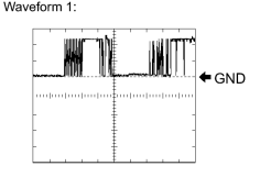
Pulse generation (see waveform 1) |
|||
|
E18-9 (TXCT) - E18-8 (AGND) |
SB - L |
Key code input signal |
Key not in cabin |
Below 1 V |
|
Engine switch pressed and key held close to engine switch* |
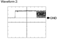
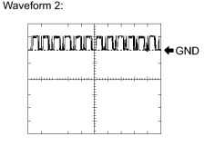
Pulse generation (see waveform 2) |
HINT:
*: Remove the key battery before performing this inspection.
If the result is not as specified, the switch may have a malfunction.
|
(e) Using an oscilloscope, check waveform 1.
HINT:
*: Remove the key battery before performing this inspection. |
|
(f) Using an oscilloscope, check waveform 2.
HINT:
*: Remove the key battery before performing this inspection. |
2. CHECK CERTIFICATION ECU (SMART KEY ECU ASSEMBLY)
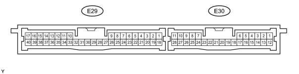
(a) Disconnect the E29 ECU connector.
(b) Measure the resistance and voltage according to the value(s) in the table below.
|
Terminal No. (Symbol) |
Wiring Color |
Terminal Description |
Condition |
Specified Condition |
|---|---|---|---|---|
|
E29 -17 (E) - Body ground |
W-B - Body ground |
Ground |
Always |
Below 1 Ω |
|
E29-1 (+B) - E29-17 (E) |
B - W-B |
+B power supply |
Always |
11 to 14 V |
|
E29-18 (IG) - E29-17 (E) |
B - W-B |
Ignition power supply |
Engine switch off |
Below 1 V |
|
Engine switch on (IG) |
11 to 14 V |
If the result is not as specified, there may be a malfunction on the wire harness side.
(c) Reconnect the E29 ECU connector.
(d) Measure the resistance and voltage according to the value(s) in the table below.
|
Terminal No. (Symbol) |
Wiring Color |
Terminal Description |
Condition |
Specified Condition |
|---|---|---|---|---|
|
E29-40 (AGND) - Body ground |
L - Body ground |
Engine switch ground |
Always |
Below 1 Ω |
|
E29-30 (VC5) - E29-40 (AGND) |
P - L |
Engine switch power supply |
Key not in cabin |
Below 1 V |
|
Engine switch pressed* |
4.6 to 5.4 V |
|||
|
E29-9 (CODE) - E29-40 (AGND) |
G- L |
Engine switch CODE input |
Key not in cabin |
Below 1 V |
|
Engine switch pressed and key held close to engine switch* |
Pulse generation (see waveform 1) |
|||
|
E29-8 (TXCT) - E29-40 (AGND) |
SB - L |
Engine switch TX output |
Key not in cabin |
Below 1 V |
|
Engine switch pressed and key held close to engine switch* |
Pulse generation (see waveform 2) |
HINT:
*: Remove the key battery before performing this inspection.
If the result is not as specified, the ECU may have a malfunction.
|
|
(e) Using an oscilloscope, check waveform 1.
HINT:
*: Remove the key battery before performing this inspection. |
|
|
(f) Using an oscilloscope, check waveform 2.
HINT:
*: Remove the key battery before performing this inspection. |
3. CHECK ID CODE BOX (IMMOBILISER CODE ECU)

(a) Disconnect the E28 box connector.
(b) Measure the resistance and voltage according to the value(s) in the table below.
|
Terminal No. (Symbol) |
Wiring Color |
Terminal Description |
Condition |
Specified Condition |
|---|---|---|---|---|
|
E28-8 (GND) - Body ground |
W-B - Body ground |
Ground |
Always |
Below 1 Ω |
|
E28-1 (+B) - E28-8 (GND) |
B - W-B |
+B power supply |
Always |
11 to 14 V |
If the result is not as specified, there may be a malfunction on the wire harness side.
(c) Reconnect the E28 box connector.
(d) Measure the voltage according to the value(s) in the table below.
|
Terminal No. (Symbol) |
Wiring Color |
Terminal Description |
Condition |
Specified Condition |
|---|---|---|---|---|
|
E28-5 (EFII) - E28-8 (GND) |
W - W-B |
ECM input signal |
Engine switch off |
Below 1 V |
|
Engine switch on (IG) |
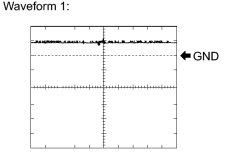
Pulse generation (see waveform 1) |
|||
|
E28-6 (EFIO) - E28-8 (GND) |
R - W-B |
ECM output signal |
Engine switch off |
Below 1 V |
|
Engine switch on (IG) |
Pulse generation (see waveform 2) |
If the result is not as specified, the ID code box (immobiliser code ECU) may have a malfunction.
|
(e) Using an oscilloscope, check waveform 1.
|
|
(f) Using an oscilloscope, check waveform 2.
|
4. CHECK MAIN BODY ECU (COWL SIDE JUNCTION BLOCK LH)
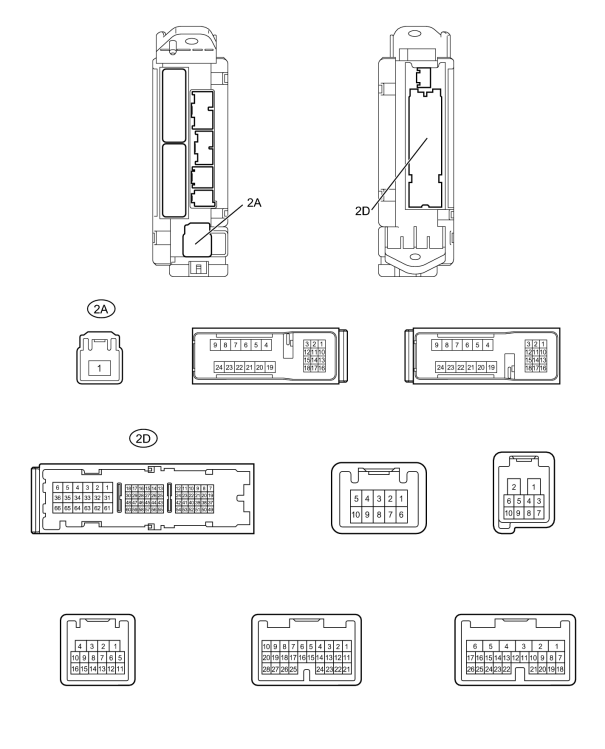
(a) Disconnect the 2D and 2A ECU connectors.
(b) Measure the resistance and voltage according to the value(s) in the table below.
|
Terminal No. (Symbol) |
Wiring Color |
Terminal Description |
Condition |
Specified Condition |
|---|---|---|---|---|
|
2D-62 (GND2) - Body ground |
W-B - Body ground |
Ground |
Always |
Below 1 Ω |
|
2D-8 (ACC) - 2D-62 (GND2) |
GR - W-B |
ACC power supply |
Engine switch off |
Below 1 V |
|
Engine switch on (ACC) |
11 to 14 V |
|||
|
2A-1 (IG) - 2D-62 (GND2) |
B - W-B |
IG power supply |
Engine switch off |
Below 1 V |
|
Engine switch on (IG) |
11 to 14 V |
If the result is not as specified, there may be a malfunction on the wire harness side.
5. CHECK STEERING LOCK ACTUATOR (STEERING LOCK ECU)

(a) Disconnect the E26 ECU connector.
(b) Measure the resistance and voltage according to the value(s) in the table below.
|
Terminal No. (Symbol) |
Wiring Color |
Terminal Description |
Condition |
Specified Condition |
|---|---|---|---|---|
|
E26-2 (SGND) - Body ground |
BR - Body ground |
Ground |
Always |
Below 1 Ω |
|
E26-1 (GND) - Body ground |
W-B - Body ground |
Ground |
Always |
Below 1 Ω |
|
E26-7 (B) - Body ground |
R - Body ground |
+B power supply |
Always |
11 to 14 V |
|
E26-6 (IG2) - Body ground |
B - Body ground |
Ignition power supply |
Engine switch off |
Below 1 V |
|
Engine switch on (IG) |
11 to 14 V |
If the result is not as specified, there may be a malfunction on the wire harness side.

|

|