Home Engine/Hybrid System Engine Control 3UR-FE ENGINE CONTROL: SFI SYSTEM
Last Modified: 11-27-2007 1.6 C
Service Category: Engine/Hybrid System Section: Engine Control
Model Year: 2008 Model: LX570 Doc ID: RM000000TA008LX
Title: 3UR-FE ENGINE CONTROL: SFI SYSTEM: DESCRIPTION (2008 LX570)

DTC

P0617

Starter Relay Circuit High

DESCRIPTION

While the engine is being cranked, the positive battery voltage is applied to terminal STA of the ECM. If the ECM detects the Starter Control (STA) signal while the vehicle is being driven, it determines that there is a malfunction in the STA circuit. The ECM then illuminates the MIL and stores the DTC.

This monitor runs when the vehicle is driven at 20 km/h (12.4 mph) for over 20 seconds.

DTC Code

DTC Detection Condition

Trouble Area

P0617

When conditions (a), (b) and (c) are met, and a positive (+B) battery voltage of 10.5 V or higher is applied to the ECM for 20 seconds (1 trip detection logic).

(a) The vehicle speed is 20 km/h (12.4 mph) or more.

(b) The engine speed is 1,000 rpm or more.

(c) The STA signal is ON.
  • Park/Neutral Position (PNP) switch
  • Starter relay circuit
  • Engine switch
  • ECM

MONITOR STRATEGY

Related DTCs

P0617: Starter signal

Required Sensors/Components (Main)

ST relay, PNP switch and engine switch

Required Sensors/Components (Related)

Vehicle Speed Sensor (VSS), Crankshaft Position (CKP) sensor

Frequency of Operation

Continuous

Duration

20 seconds

MIL Operation

Immediate

Sequence of Operation

None

TYPICAL ENABLING CONDITIONS

Monitor runs whenever following DTCs not stored

None

Battery voltage

10.5 V or higher

Vehicle speed

20 km/h (12.5 mph) or more

Engine speed

1,000 rpm or more

TYPICAL MALFUNCTION THRESHOLDS

Starter signal

ON

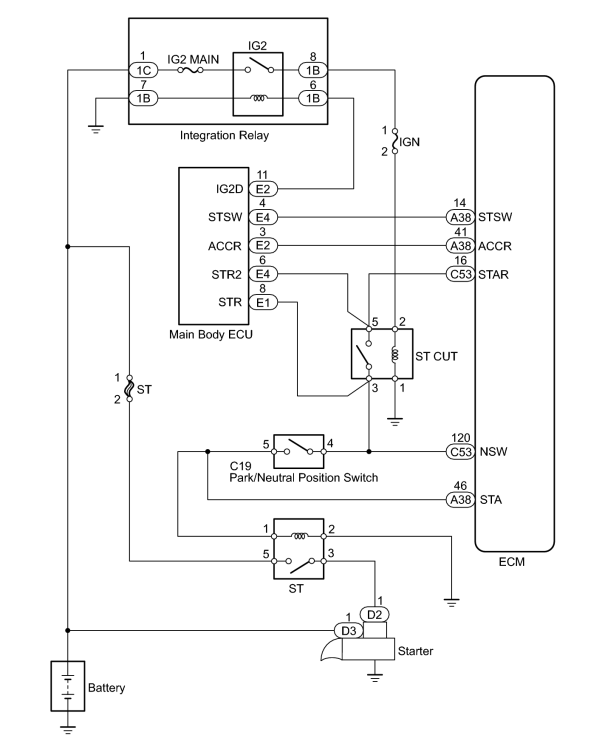
WIRING DIAGRAM


INSPECTION PROCEDURE

HINT:

PROCEDURE

1.

READ VALUE USING TECHSTREAM (STARTER SIGNAL)

(a) Connect the Techstream to the DLC3.

(b) Turn the engine switch on (IG) and turn the Techstream on.

(c) Enter the following menus: Powertrain / Engine and ECT / Data List / All Data / Starter Signal.

(d) Check the value displayed on the Techstream when the engine switch is turned to the START positions.

OK:

Engine Switch Position

Starter Signal

On (IG)

OFF

START

ON

OK

2.

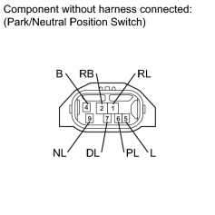
INSPECT PARK/NEUTRAL POSITION SWITCH ASSEMBLY


(a) Disconnect the C19 PNP switch connector.

(b) Measure the resistance according to the value(s) in the table below.

Standard Resistance:

Tester Connection

Condition

Specified Condition

4 (B) - 5 (L)

Shift lever in P

Below 1 Ω

Shift lever in N

Below 1 Ω

Shift lever not in P and N

10 kΩ or higher

OK

3.

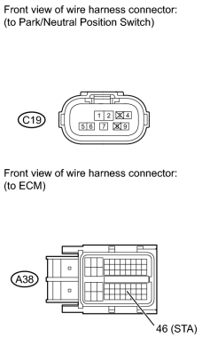
CHECK HARNESS AND CONNECTOR (PNP SWITCH - ECM)


(a) Disconnect the C19 PNP switch connector.

(b) Disconnect the A38 ECM connector.

(c) Measure the resistance according to the value(s) in the table below.

Standard Resistance:

Tester Connection

Condition

Specified Condition

C19-5 - A38-46 (STA)

Always

Below 1 Ω

C19-5 or A38-46 (STA) - Body ground

Always

10 kΩ or higher

OK