| Last Modified: 11-27-2007 | 1.6 F | |
| Service Category: General | Section: Introduction | |
| Model Year: 2008 | Model: LX570 | Doc ID: RM000000UZ205CX |
| Title: INTRODUCTION: HOW TO TROUBLESHOOT ECU CONTROLLED SYSTEMS: GENERAL INFORMATION (2008 LX570) | ||
GENERAL INFORMATION
A large number of ECU controlled systems are used in the LEXUS LX570. In general, ECU controlled systems are considered to be very intricate, requiring a high level of technical knowledge to troubleshoot. However, most problem checking procedures only involve inspecting the ECU controlled system circuits one by one. An adequate understanding of the system and a basic knowledge of electricity is enough to perform effective troubleshooting, accurate diagnoses and necessary repairs.
DIAGNOSTIC TESTER
1. DESCRIPTION
System data and the Diagnostic Trouble Codes (DTCs) can be read from the Data Link Connector 3 (DLC3) of the vehicle. When the system seems to be malfunctioning, use the Techstream to check for a malfunction and perform repairs.
HINT:
Techstream is the name for the diagnostic tester in North America.
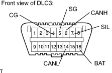
2. DATA LINK CONNECTOR 3 (DLC3)
|
(a) The vehicle ECU uses the ISO 15765-4 communication protocol. The terminal arrangement of the DLC3 complies with SAE J1962 and matches the ISO 15765-4 format.
NOTICE:
*1: Disconnect the cable from the negative (-) battery terminal before measuring the resistance.
*2: Before measuring the resistance, leave the vehicle as is for at least 1 minute and do not operate the engine switch, any other switches, or the doors.
If the result is not as specified, the DLC3 may have a malfunction. Repair or replace the harness and connector. |
(b) Connect the cable of the Techstream to the DLC3, turn the engine switch on and attempt to use the Techstream. If the display indicates that a communication error has occurred, there is a problem either with the vehicle or with the Techstream.
HINT:
- If communication is normal when the Techstream is connected to another vehicle, inspect the DLC3 of the original vehicle.
- If communication is still not possible when the Techstream is connected to another vehicle, the problem may be in the Techstream itself. Consult the Service Department listed in the Techstream's instruction manual.

|

|