| Last Modified: 11-27-2007 | 1.6 J | |
| Service Category: Vehicle Interior | Section: Theft Deterrent/Keyless Entry | |
| Model Year: 2008 | Model: LX570 | Doc ID: RM000000W1200PX |
| Title: THEFT DETERRENT / KEYLESS ENTRY: THEFT DETERRENT SYSTEM: DESCRIPTION (2008 LX570) | ||
|
Security Indicator Light Circuit |
DESCRIPTION
When the theft deterrent system is in the disarmed state, the security indicator will flash continuously if the immobiliser system is set, or not illuminate if the immobiliser system is not set.
When the theft deterrent system is in the armed state, the immobiliser system is automatically set and the security indicator will flash continuously.
When the theft deterrent system is in the arming preparation state and alarm sounding state, the certification ECU (smart key ECU assembly) causes the security indicator to be illuminated.
WIRING DIAGRAM
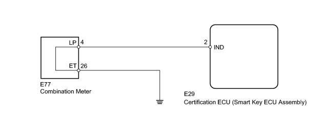
INSPECTION PROCEDURE
PROCEDURE
|
1. |
PERFORM ACTIVE TEST USING TECHSTREAM (SECURITY INDICATOR) |
(a) Operate the Techstream according to the steps on the display and select "Active Test".
Smart Access
|
Tester Display |
Test Part |
Control Range |
Diagnostic Note |
|---|---|---|---|
|
Security Indicator |
Security indicator |
ON / OFF |
- |
OK:
Security indicator illuminates.
|

|
2. |
CHECK HARNESS AND CONNECTOR (COMBINATION METER - CERTIFICATION ECU [SMART KEY ECU ASSEMBLY] AND BODY GROUND) |
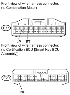
(a) Disconnect the E77 meter connector.
(b) Disconnect the E29 ECU connector.
(c) Measure the resistance according to the value(s) in the table below.
Standard Resistance:
|
Tester Connection |
Condition |
Specified Condition |
|---|---|---|
|
E77-4 (LP) - E29-2 (IND) |
Always |
Below 1 Ω |
|
E77-26 (ET) - Body ground |
Always |
Below 1 Ω |
|
E77-4 (LP) or E29-2 (IND) - Body ground |
Always |
10 kΩ or higher |
|

|

|