| Last Modified: 11-27-2007 | 1.6 J | |
| Service Category: Vehicle Interior | Section: Door Lock | |
| Model Year: 2008 | Model: LX570 | Doc ID: RM000000W1Z00QX |
| Title: DOOR LOCK: POWER DOOR LOCK CONTROL SYSTEM: DESCRIPTION (2008 LX570) | ||
|
All Doors LOCK/UNLOCK Functions do not Operate Via Door Control Switch |
DESCRIPTION
The main body ECU receives switch signals from the door control switch and activates the door lock motor on each door according to these signals.
WIRING DIAGRAM
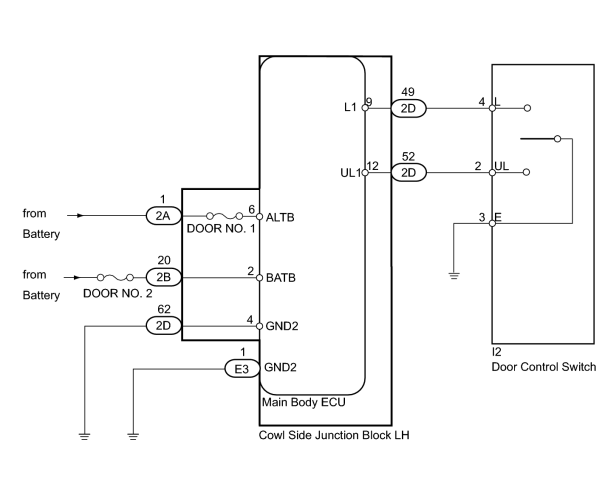
INSPECTION PROCEDURE
PROCEDURE
|
1. |
READ VALUE USING TECHSTREAM (DOOR LOCK AND UNLOCK SWITCH) |
(a) Use the Data List to check if the door lock and unlock switches are functioning properly.
Main Body ECU
|
Tester Display |
Measurement Item/Range |
Normal Condition |
Diagnostic Note |
|---|---|---|---|
|
Door Lock SW-Lock |
Door manual lock switch signal / ON or OFF |
ON: Front passenger side door control switch on (lock) OFF: Front passenger side door control switch off |
- |
|
Door Unlock SW-Unlock |
Door manual unlock switch signal / ON or OFF |
ON: Front passenger side door control switch on (unlock) OFF: Front passenger side door control switch off |
- |
OK:
On the Techstream screen, each item changes between ON and OFF according to above chart.
|

|
2. |
INSPECT FUSE (DOOR NO. 1, DOOR NO. 2) |
(a) Remove the DOOR NO. 1 fuse from the main body ECU.
(b) Remove the DOOR NO. 2 fuse from the engine room No. 1 relay block.
(c) Measure the resistance according to the value(s) in the table below.
Standard Resistance:
|
Tester Connection |
Condition |
Specified Condition |
|---|---|---|
|
DOOR NO. 1 fuse |
Always |
Below 1 Ω |
|
DOOR NO. 2 fuse |
Always |
Below 1 Ω |
|
|
3. |
CHECK HARNESS AND CONNECTOR (MAIN BODY ECU - BATTERY AND BODY GROUND) |
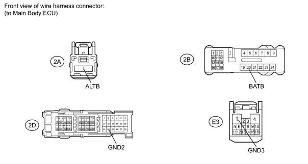
(a) Disconnect the 2A, 2B, 2D and E3 ECU connectors.
(b) Measure the voltage according to the value(s) in the table below.
Standard Voltage:
|
Tester Connection |
Condition |
Specified Condition |
|---|---|---|
|
2A-1 (ALTB) - Body ground |
Always |
11 to 14 V |
|
2B-20 (BATB) - Body ground |
Always |
11 to 14 V |
(c) Measure the resistance according to the value(s) in the table below.
Standard Resistance:
|
Tester Connection |
Condition |
Specified Condition |
|---|---|---|
|
2D-62 (GND2) - Body ground |
Always |
Below 1 Ω |
|
E3-1 (GND3) - Body ground |
Always |
Below 1 Ω |
|
|
4. |
INSPECT DOOR CONTROL SWITCH ASSEMBLY (DOOR LOCK AND UNLOCK SWITCH) |
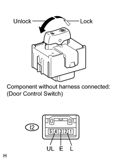
(a) Remove the door control switch
 .
.
(b) Measure the resistance according to the value(s) in the table below.
Standard Resistance:
|
Tester Connection |
Switch Condition |
Specified Condition |
|---|---|---|
|
4 (L) - 3 (E) |
Lock |
Below 1 Ω |
|
2 (UL) - I3 (E) 4 (L) - 3 (E) |
Off |
10 kΩ or higher |
|
2 (UL) - 3 (E) |
Unlock |
Below 1 Ω |
|
|
5. |
CHECK HARNESS AND CONNECTOR (DOOR CONTROL SWITCH - MAIN BODY ECU AND BODY GROUND) |
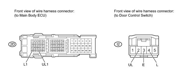
(a) Disconnect the 2D ECU connector.
(b) Disconnect the I2 switch connector.
(c) Measure the resistance according to the value(s) in the table below.
Standard Resistance:
|
Tester Connection |
Condition |
Specified Condition |
|---|---|---|
|
2D-52 (UL1) - I2-2 (UL) |
Always |
Below 1 Ω |
|
2D-49 (L1) - I2-4 (L) |
Always |
Below 1 Ω |
|
I2-2 (UL) - Body ground |
Always |
10 kΩ or higher |
|
I2-3 (E) - Body ground |
Always |
Below 1 Ω |
|
I2-4 (L) - Body ground |
Always |
10 kΩ or higher |
|

|

|