- Engine switch on (IG)
- Transfer position switch on L4
| Last Modified: 11-27-2007 | 1.6 U | |
| Service Category: Drivetrain | Section: Automatic Transmission/Transaxle | |
| Model Year: 2008 | Model: LX570 | Doc ID: RM000000W74075X |
| Title: AB60F AUTOMATIC TRANSMISSION / TRANSAXLE: AUTOMATIC TRANSMISSION SYSTEM: TERMINALS OF ECM (2008 LX570) | ||
TERMINALS OF ECM
1. CHECK ECM
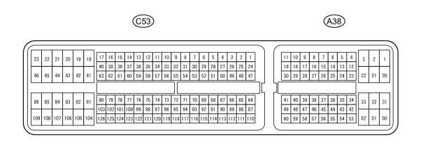
HINT:
Each ECM terminal standard voltage is shown in the table below.
In the table, first follow the information under "Condition". Look under "Terminal No. (Symbol)" for the terminals to be inspected. The standard voltage between the terminals is shown under "Specified Condition".
Use the illustration above as a reference for the ECM terminals.
|
Terminal No. (Symbol) |
Wiring Color |
Terminal Description |
Condition |
Specified Condition |
|---|---|---|---|---|
|
A38-21 (L4) - C53-81 (E1) |
BR-R - W-B |
Transfer L4 position signal |
|
Below 1.5 V |
|
A38-21 (L4) - C53-81 (E1) |
BR-R - W-B |
Transfer L4 position signal |
|
11 to 14 V |
|
A38-5 (TFN) - C53-81 (E1) |
G - W-B |
Transfer neutral position signal |
|
Below 1.5 V |
|
A38-5 (TFN) - C53-81 (E1) |
G - W-B |
Transfer neutral position signal |
|
11 to 14 V |
|
C53-120 (NSW) - C53-81 (E1) |
L - W-B |
PNP switch signal |
|
Below 1 V |
|
C53-120 (NSW) - C53-81 (E1) |
L - W-B |
PNP switch signal |
|
11 to 14 V |
|
C53-2 (P) - C53-81 (E1) |
G-B - W-B |
P shift position switch signal |
|
11 to 14 V |
|
C53-2 (P) - C53-81 (E1) |
G-B - W-B |
P shift position switch signal |
|
Below 1 V |
|
C53-26 (R) - C53-81 (E1) |
L-R - W-B |
R shift position switch signal |
|
11 to 14 V |
|
C53-26 (R) - C53-81 (E1) |
L-R - W-B |
R shift position switch signal |
|
Below 1 V |
|
C53-25 (N) - C53-81 (E1) |
G-W - W-B |
N shift position switch signal |
|
11 to 14 V |
|
C53-25 (N) - C53-81 (E1) |
G-W - W-B |
N shift position switch signal |
|
Below 1 V |
|
C53-27 (D) - C53-81 (E1) |
G - W-B |
D shift position switch signal |
|
11 to 14 V |
|
C53-27 (D) - C53-81 (E1) |
G - W-B |
D shift position switch signal |
|
Below 1 V |
|
A38-25 (S) - C53-81 (E1) |
W - W-B |
S shift position switch signal |
|
11 to 14 V |
|
A38-25 (S) - C53-81 (E1) |
W - W-B |
S shift position switch signal |
|
Below 1 V |
|
A38-38 (SFTU) - C53-81 (E1) |
Y - W-B |
Up-shift position switch signal |
|
11 to 14 V |
|
A38-38 (SFTU) - C53-81 (E1) |
Y - W-B |
Up-shift position switch signal |
|
Below 1 V |
|
A38-27 (SFTD) - C53-81 (E1) |
L - W-B |
Down-shift position switch signal |
|
11 to 14 V |
|
A38-27 (SFTD) - C53-81 (E1) |
L - W-B |
Down-shift position switch signal |
|
Below 1 V |
|
A38-36 (STP) - C53-81 (E1) |
R - W-B |
Stop light switch signal |
Brake pedal depressed |
11 to 14 V |
|
A38-36 (STP) - C53-81 (E1) |
R - W-B |
Stop light switch signal |
Brake pedal released |
Below 1.5 V |
|
C53-7 (S1) - C53-81 (E1) |
R - W-B |
Shift solenoid valve S1 signal |
1st gear |
Below 1 V |
|
C53-7 (S1) - C53-81 (E1) |
R - W-B |
Shift solenoid valve S1 signal |
Not in 1st gear |
11 to 14 V |
|
C53-6 (S2) - C53-81 (E1) |
W - W-B |
Shift solenoid valve S2 signal |
1st, 2nd or 6th gear |
11 to 14 V |
|
C53-6 (S2) - C53-81 (E1) |
W - W-B |
Shift solenoid valve S2 signal |
3rd, 4th or 5th gear |
Below 1 V |
|
C53-3 (S3) - C53-81 (E1) |
B-R - W-B |
Shift solenoid valve S3 signal |
1st, 2nd or 3rd gear |
11 to 14 V |
|
C53-3 (S3) - C53-81 (E1) |
B-R - W-B |
Shift solenoid valve S3 signal |
4th, 5th or 6th gear |
Below 1 V |
|
C53-5 (S4) - C53-81 (E1) |
G-R - W-B |
Shift solenoid valve S4 signal |
5th or 6th gear |
11 to 14 V |
|
C53-5 (S4) - C53-81 (E1) |
G-R - W-B |
Shift solenoid valve S4 signal |
1st, 2nd, 3rd or 4th gear |
Below 1 V |
|
C53-4 (SR) - C53-81 (E1) |
G - W-B |
Shift solenoid valve SR signal |
1st, 2nd, 3rd or 4th gear |
11 to 14 V |
|
C53-4 (SR) - C53-81 (E1) |
G - W-B |
Shift solenoid valve SR signal |
5th or 6th gear |
Below 1 V |
|
C53-14 (SL1+) - C53-15 (SL1-) |
Y - L |
Shift solenoid valve SL1 signal |
5th or 6th gear |
Pulse generation (see waveform 1) |
|
C53-12 (SL2+) - C53-13 (SL2-) |
G-R - L-W |
Shift solenoid valve SL2 signal |
Engine idling |
Pulse generation (see waveform 2) |
|
C53-9 (SLT+) - C53-8 (SLT-) |
B - G-B |
Shift solenoid valve SLT signal |
Engine idling |
Pulse generation (see waveform 3) |
|
C53-10 (SLU+) - C53-11 (SLU-) |
L-Y - L-R |
Shift solenoid valve SLU signal |
5th (lock-up) gear or 6th (lock-up) gear |
Pulse generation (see waveform 4) |
|
C53-122 (THO1) - C53-98 (ETHA) |
G-Y - BR |
No. 1 ATF temperature sensor signal |
No. 1 ATF temperature: 115°C (239°F) or higher |
Below 1.5 V |
|
C53-99 (THO2) - C53-98 (ETHA) |
L - BR |
No. 2 ATF temperature sensor signal |
No. 2 ATF temperature: 115°C (239°F) or higher |
Below 1.5 V |
|
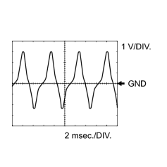
C53-101 (SP2+) - C53-100 (SP2-) |
Y - B |
Speed sensor SP2 signal |
Vehicle speed 20 km/h (12 mph) |
Pulse generation (see waveform 5) |
|
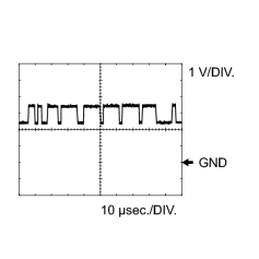
C53-124 (NT+) - C53-123 (NT-) |
Y - B |
Speed sensor NT signal |
Engine idling (shift lever in P or N) |
Pulse generation (see waveform 6) |
|
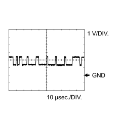
A38-10 (CANH) - C53-81 (E1) |
P - W-B |
CAN communication line |
Engine switch on (IG) |
Pulse generation (see waveform 7) |
|
A38-11 (CANL) - C53-81 (E1) |
B - W-B |
CAN communication line |
Engine switch on (IG) |
Pulse generation (see waveform 8) |
|
A38-51 (PWR) - C53-81 (E1) |
L-B - W-B |
Pattern select switch (PWR) signal |
|
11 to 14 V |
|
A38-51 (PWR) - C53-81 (E1) |
L-B - W-B |
Pattern select switch (PWR) signal |
|
Below 1.5 V |
|
A38-4 (SNWI) - C53-81 (E1) |
R - W-B |
Pattern select switch (2ND) signal |
|
11 to 14 V |
|
A38-4 (SNWI) - C53-81 (E1) |
R - W-B |
Pattern select switch (2ND) signal |
|
Below 1.5 V |
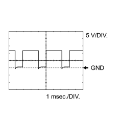
|
(a) Using an oscilloscope, check waveform 1.
|
|
|
(b) Using an oscilloscope, check waveform 2.
|
|
|
(c) Using an oscilloscope, check waveform 3.
|
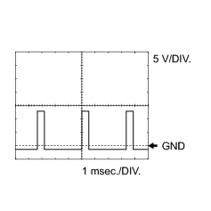
|
(d) Using an oscilloscope, check waveform 4.
|
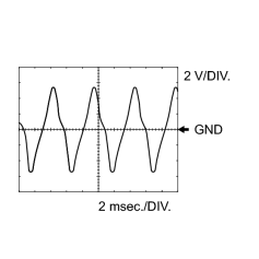
|
(e) Using an oscilloscope, check waveform 5.
|
|
(f) Using an oscilloscope, check waveform 6.
|
|
(g) Using an oscilloscope, check waveform 7.
|
|
(h) Using an oscilloscope, check waveform 8.
|

|

|