- Shift solenoid valve SLT remains open or closed
- Shift solenoid valve S1, S2, S3, S4 or SL2 remains open or closed
- Gear 6 incorrect ratio (sequence valve) or 1-2 shift valve is stuck
- Valve body is blocked
- Automatic transmission (clutch, brake, gear, etc.)
| Last Modified: 11-27-2007 | 1.6 C | |
| Service Category: Drivetrain | Section: Automatic Transmission/Transaxle | |
| Model Year: 2008 | Model: LX570 | Doc ID: RM000000W8305RX |
| Title: AB60F AUTOMATIC TRANSMISSION / TRANSAXLE: AUTOMATIC TRANSMISSION SYSTEM: DESCRIPTION (2008 LX570) | ||
|
DTC |
P0894 |
Transmission Component Slipping |
|
DTC |
P2714 |
Pressure Control Solenoid "D" Performance (Shift Solenoid Valve SLT) |
DESCRIPTION
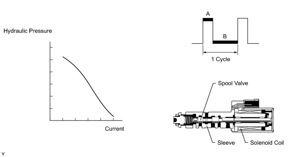
The shift solenoid valve (SLT) controls the transmission line pressure for smooth transmission operation based on signals from the throttle position sensor and vehicle speed sensor. The ECM adjusts the duty ratio* of shift solenoid valve SLT to control the hydraulic line pressure coming from the primary regulator valve. Appropriate line pressure assures smooth shifting with varying engine outputs.
HINT:
*: The duty ratio is the ratio of the current ON time (A) to the total of the current ON and OFF time (A + B).
Duty Ratio (%) = A / (A + B) x 100
|
DTC Code |
DTC Detection Condition |
Trouble Area |
|---|---|---|
|
P0894 |
The ECM detects a malfunction of shift solenoid valve SLT, S1, S2, S3, S4, SL2, gear 6 incorrect ratio (sequence valve) or 1-2 shift valves according to the revolution difference of the turbine and output shaft, and also by the oil pressure (2-trip detection logic). |
|
|
P2714 |
The ECM detects a malfunction of shift solenoid valve SLT (ON side) according to the revolution difference of the turbine and output shaft, and also by the oil pressure (2 trip detection logic). |
|
MONITOR DESCRIPTION
The ECM calculates the amount of heat absorbed by the friction material based on the difference in revolution (clutch slippage) between the turbine and output shaft. The ECM illuminates the MIL and stores these DTCs when the amount of heat absorption exceeds the specified value.
There are 2 causes of revolution difference.
- When shift solenoid valve SLT remains ON, oil pressure decreases, which causes the clutch engagement force to decrease.
- When the shift solenoid valve remains ON or OFF, the gear position commanded by the ECM and the actual gear position are not the same.
NOTICE:
If you continue driving under these conditions, the clutch will burn out and the vehicle will no longer be drivable.
MONITOR STRATEGY
|
Related DTCs |
P0894: Automatic transmission slip malfunction P2714: Shift solenoid valve SLT/ON malfunction |
|
Required sensors/Components |
Shift solenoid valve SLT |
|
Frequency of operation |
Continuous |
|
Duration |
P0894 ON malfunction (A): Immediately P0894 ON malfunction (B): 0.4 sec. P2714: Immediately |
|
MIL operation |
2 driving cycles |
|
Sequence of operation |
None |
TYPICAL ENABLING CONDITIONS
ALL
|
The monitor will run whenever the following DTCs are not stored |
None |
|
Turbine speed sensor circuit |
Not circuit malfunction |
|
Output speed sensor circuit |
Not circuit malfunction |
|
ATF temperature sensor circuit |
Not circuit malfunction |
|
Shift solenoid valve S1 circuit |
Not circuit malfunction |
|
Shift solenoid valve S2 circuit |
Not circuit malfunction |
|
Shift solenoid valve S3 circuit |
Not circuit malfunction |
|
Shift solenoid valve S4 circuit |
Not circuit malfunction |
|
Shift solenoid valve SR circuit |
Not circuit malfunction |
|
Shift solenoid valve SL1 circuit |
Not circuit malfunction |
|
Shift solenoid valve SL2 circuit |
Not circuit malfunction |
|
Shift solenoid valve SLT circuit |
Not circuit malfunction |
|
ECT (Engine Coolant Temperature) sensor circuit |
Not circuit malfunction |
|
KCS sensor circuit |
Not circuit malfunction |
|
ETCS (Electric Throttle Control System) |
Not system down |
|
Transmission position |
D |
|
Duration time from shifting N to D |
4 sec. or more |
|
ECT |
40°C (104°F) or higher |
|
Spark advance from max. retard timing by KCS control |
0° crankshaft angle or more |
|
Engine |
Starting |
|
Transfer position |
HIGH* |
HINT:
*: Following conditions met
|
Vehicle speed sensor circuit |
Not circuit malfunction |
|
Output shaft speed sensor circuit |
Not circuit malfunction |
|
Transfer output speed |
143 rpm or more |
|
Transfer input speed/Transfer output speed (NO/NOtf) |
0.9 or more, and less than 1.1 |
TYPICAL MALFUNCTION THRESHOLDS
[P0894: ON malfunction]
When either condition below is met: ON malfunction (A) or (B)
ON malfunction (A)
|
Summation of C1 clutch heat generations |
Specified value |
ON malfunction (B)
|
Summation of C2 clutch heat generations |
Specified value |
|
Actual gear for SLT failure judgment |
Not determined |
[P2714: ON malfunction]
When one of following conditions is met: ON malfunction (A), (B), (C), (D), (E), (F), (G) or (H)
ON malfunction (A)
|
Summation of C1 clutch heat generations |
Specified value |
ON malfunction (B)
|
Shift solenoid valve S1 OFF malfunction |
Detected |
ON malfunction (C)
|
Shift solenoid valve S2 OFF malfunction |
Detected |
ON malfunction (D)
|
Shift solenoid valve S3 ON malfunction |
Detected |
ON malfunction (E)
|
Shift solenoid valve S4 OFF malfunction |
Detected |
ON malfunction (F)
|
1-2 shift valve malfunction |
Detected |
ON malfunction (G)
|
Sequence valve malfunction |
Detected |
ON malfunction (H)
|
Shift solenoid valve SL2 ON malfunction |
Detected |
INSPECTION PROCEDURE
PROCEDURE
|
1. |
CHECK DTC OUTPUT (IN ADDITION TO DTCS P0894 AND P2714) |
(a) Connect the Techstream to the DLC3.
(b) Turn the engine switch on (IG).
(c) Turn the Techstream on.
(d) Enter the following menus: Powertrain / Engine and ECT / Trouble Codes.
(e) Read the DTCs using the Techstream.
Result
|
Result |
Proceed to |
|---|---|
|
A |
|
P0894, P2714 and other DTCs are output |
B |
HINT:
If any other codes besides P0894 and P2714 are output, perform troubleshooting for those DTCs first.
|

|
2. |
PERFORM ACTIVE TEST USING TECHSTREAM (SHIFT SOLENOID VALVE SLT) |
NOTICE:
- Perform the test at the normal operating ATF temperature: 50 to 80°C (122 to 176°F).
- Be careful to prevent SST hose from interfering with the exhaust pipe.
- Perform the test with the A/C turned off.
HINT:
Using the Techstream to perform Active Tests allows relays, VSVs, actuators and other items to be operated without removing any parts. This non-intrusive functional inspection can be very useful because intermittent operation may be discovered before parts or wiring is disturbed. Performing Active Tests early in troubleshooting is one way to save diagnostic time. Data List information can be displayed while performing Active Tests.
|
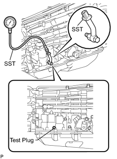
(a) Remove the test plug on the transmission case center right side and connect SST. |
SST: 09992-00095
09992-00231
09992-00271
(b) Connect the Techstream to the DLC3.
(c) Start the engine and warm it up.
(d) Measure the line pressure with SST.
(e) Turn the Techstream on.
(f) Enter the following menus: Powertrain / Engine and ECT / Active Test.
(g) According to the display on the Techstream, perform the Active Test.
(h) Measure the line pressure.
Engine and ECT
|
Tester Display |
Test Part |
Control Range |
Diagnostic Note |
|---|---|---|---|
|
Activate the Solenoid (SLT)* |
Operate shift solenoid valve SLT and raise line pressure |
ON or OFF HINT:
|
[Vehicle Condition]
|
HINT:
*: Activate the Solenoid (SLT) in the Active Test is performed to check the line pressure changes by connecting SST to the automatic transmission, which is used in the Hydraulic Test
 as well. Note that the pressure values in the Active Test and hydraulic test are different.
OK:
The line pressure changes as specified when performing the Active Test.
|
|
3. |
PERFORM ACTIVE TEST USING TECHSTREAM (RUNNING TEST) |
CAUTION:
This test should always be performed with at least 2 people.
NOTICE:
- Perform the test at the normal operating ATF temperature: 50 to 80°C (122 to 176°F).
- Perform the test with the A/C turned off.
HINT:
Using the Techstream to perform Active Tests allows relays, VSVs, actuators and other items to be operated without removing any parts. This non-intrusive functional inspection can be very useful because intermittent operation may be discovered before parts or wiring is disturbed. Performing Active Tests early in troubleshooting is one way to save diagnostic time. Data List information can be displayed while performing Active Tests.
(a) Connect the Techstream to the DLC3.
(b) Clear the DTC
.
(c) Warm up the engine.
(d) Enter the following menus: Powertrain / Engine and ECT / Active Test.
(e) According to the display on the Techstream, perform the Active Test.
HINT:
While driving, the shift position can be forcibly changed with the Techstream.
Engine and ECT
|
Tester Display |
Test Part |
Control Range |
Diagnostic Note |
|---|---|---|---|
|
Control the Shift Position |
Operate shift solenoid valve and set each shift position |
|
It is possible to check the operation of the shift solenoid valves. [Vehicle Condition] The vehicle speed is 50 km/h (31 mph) or less. |
HINT:
- This test can be conducted when the vehicle speed is 50 km/h (31 mph) or less.
- The 4th to 5th and 5th to 6th up-shifts must be performed with the accelerator pedal released.
- The 6th to 5th and 5th to 4th down-shifts must be performed with the accelerator pedal released.
- Do not operate the accelerator pedal for at least 2 seconds after shifting and do not shift successively.
- The shift position commanded by the ECM is shown in the Data List display on the Techstream.
(f) Compare the ECM gear shift command and the actual gear position.
OK:
Gear position changes in accordance with the Techstream command.
Result
|
System Condition |
ECM Gear Shift Command |
Proceed to |
|||||||
|---|---|---|---|---|---|---|---|---|---|
|
1st |
2nd |
3rd |
4th |
5th |
6th |
||||
|
Malfunction |
Shift solenoid valve S1 |
Stuck ON*1 |
2nd |
2nd |
3rd |
4th |
5th |
6th |
A |
|
Stuck OFF |
1st |
1st |
3rd |
4th |
5th |
N*2 |
|||
|
Shift solenoid valve S2 |
Stuck ON |
1st |
2nd |
2nd |
4th |
6th |
6th |
B |
|
|
Stuck OFF |
3rd |
3rd |
3rd |
4th |
5th |
5th |
|||
|
Shift solenoid valve S3 |
Stuck ON |
1st |
2nd |
3rd |
3rd |
N*2 |
N*2 |
C |
|
|
Stuck OFF |
3rd |
4th |
4th |
4th |
5th |
6th |
|||
|
Shift solenoid valve S4 |
Stuck ON*3 |
1st |
2nd |
3rd |
4th |
5th |
6th |
D |
|
|
Stuck OFF |
1st |
2nd |
3rd |
4th |
4th |
4th |
|||
|
Normal |
1st |
2nd |
3rd |
4th |
5th |
6th |
E |
||
HINT:
- *1: When shift solenoid valve S1 is stuck ON, the vehicle cannot drive in reverse.
- *2: Neutral
- *3: When shift solenoid valve S4 is stuck ON, gear shifting is normal.
|
|
4. |
INSPECT SHIFT SOLENOID VALVE S1 |
|
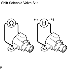
(a) Remove shift solenoid valve S1. |
(b) Measure the resistance according to the value(s) in the table below.
Standard Resistance:
|
Tester Connection |
Condition |
Specified Condition |
|---|---|---|
|
Shift solenoid valve S1 connector terminal - Shift solenoid valve S1 body |
20°C (68°F) |
11 to 15 Ω |
(c) Apply battery voltage (12 V) to the shift solenoid valve and check that the valve moves and makes an operating noise.
OK:
|
Measurement Condition |
Specified Condition |
|---|---|
|
Valve moves and makes an operating noise |
|
|
5. |
INSPECT TRANSMISSION VALVE BODY ASSEMBLY |
(a) Check the transmission valve body assembly
.
OK:
There are no foreign objects on any valve.
|
|
6. |
INSPECT TORQUE CONVERTER CLUTCH ASSEMBLY |
(a) Check the torque converter clutch assembly
.
OK:
The torque converter clutch operates normally.
|
|
8. |
INSPECT SHIFT SOLENOID VALVE S2 |
|
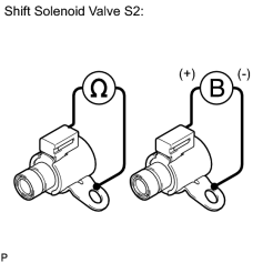
(a) Remove shift solenoid valve S2. |
(b) Measure the resistance according to the value(s) in the table below.
Standard Resistance:
|
Tester Connection |
Condition |
Specified Condition |
|---|---|---|
|
Shift solenoid valve S2 connector terminal - Shift solenoid valve S2 body |
20°C (68°F) |
11 to 15 Ω |
(c) Apply battery voltage (12 V) to the shift solenoid valve and check that the valve moves and makes an operating noise.
OK:
|
Measurement Condition |
Specified Condition |
|---|---|
|
Valve moves and makes an operating noise |
|
|
9. |
INSPECT TRANSMISSION VALVE BODY ASSEMBLY |
(a) Check the transmission valve body assembly
.
OK:
There are no foreign objects on any valve.
|
|
10. |
INSPECT TORQUE CONVERTER CLUTCH ASSEMBLY |
(a) Check the torque converter clutch assembly
.
OK:
The torque converter clutch operates normally.
|
|
12. |
INSPECT SHIFT SOLENOID VALVE S3 |
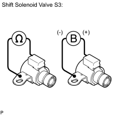
|
(a) Remove shift solenoid valve S3. |
(b) Measure the resistance according to the value(s) in the table below.
Standard Resistance:
|
Tester Connection |
Condition |
Specified Condition |
|---|---|---|
|
Shift solenoid valve S3 connector terminal - Shift solenoid valve S3 body |
20°C (68°F) |
11 to 15 Ω |
(c) Apply battery voltage (12 V) to the shift solenoid valve and check that the valve moves and makes an operating noise.
OK:
|
Measurement Condition |
Specified Condition |
|---|---|
|
Valve moves and makes an operating noise |
|
|
13. |
INSPECT TRANSMISSION VALVE BODY ASSEMBLY |
(a) Check the transmission valve body assembly
.
OK:
There are no foreign objects on any valve.
|
|
14. |
INSPECT TORQUE CONVERTER CLUTCH ASSEMBLY |
(a) Check the torque converter clutch assembly
.
OK:
The torque converter clutch operates normally.
|
|
16. |
INSPECT SHIFT SOLENOID VALVE S4 |
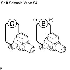
|
(a) Remove shift solenoid valve S4. |
(b) Measure the resistance according to the value(s) in the table below.
Standard Resistance:
|
Tester Connection |
Condition |
Specified Condition |
|---|---|---|
|
Shift solenoid valve S4 connector terminal - Shift solenoid valve S4 body |
20°C (68°F) |
11 to 15 Ω |
(c) Apply battery voltage (12 V) to the shift solenoid valve and check that the valve moves and makes an operating noise.
OK:
|
Measurement Condition |
Specified Condition |
|---|---|
|
Valve moves and makes an operating noise |
|
|
17. |
INSPECT SHIFT SOLENOID VALVE SL2 |
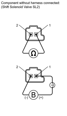
|
(a) Remove shift solenoid valve SL2. |
(b) Measure the resistance according to the value(s) in the table below.
Standard Resistance:
|
Tester Connection |
Condition |
Specified Condition |
|---|---|---|
|
1 - 2 |
20°C (68°F) |
5.0 to 5.6 Ω |
(c) Apply battery voltage (12 V) to the shift solenoid valve and check that the valve moves and makes an operating noise.
OK:
|
Measurement Condition |
Specified Condition |
|---|---|
|
Valve moves and makes an operating noise |
|
|
18. |
INSPECT TRANSMISSION VALVE BODY ASSEMBLY |
(a) Check the transmission valve body assembly
.
OK:
There are no foreign objects on any valve.
|
|
19. |
INSPECT TORQUE CONVERTER CLUTCH ASSEMBLY |
(a) Check the torque converter clutch assembly
.
OK:
The torque converter clutch operates normally.
|
|
21. |
INSPECT SHIFT SOLENOID VALVE SLT |
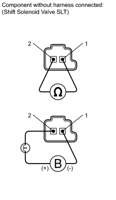
|
(a) Remove shift solenoid valve SLT. |
(b) Measure the resistance according to the value(s) in the table below.
Standard Resistance:
|
Tester Connection |
Condition |
Specified Condition |
|---|---|---|
|
1 - 2 |
20°C (68°F) |
5.0 to 5.6 Ω |
(c) Apply battery voltage (12 V) to the shift solenoid valve and check that the valve moves and makes an operating noise.
OK:
|
Measurement Condition |
Specified Condition |
|---|---|
|
Valve moves and makes an operating noise |
|
|
22. |
INSPECT TRANSMISSION VALVE BODY ASSEMBLY |
(a) Check the transmission valve body assembly
.
OK:
There are no foreign objects on any valve.
|
|
23. |
INSPECT TORQUE CONVERTER CLUTCH ASSEMBLY |
(a) Check the torque converter clutch assembly
.
OK:
The torque converter clutch operates normally.
|

|

|