- Short in shift solenoid valve SR circuit
- Shift solenoid valve SR
- ECM
| Last Modified: 11-27-2007 | 1.6 C | |
| Service Category: Drivetrain | Section: Automatic Transmission/Transaxle | |
| Model Year: 2008 | Model: LX570 | Doc ID: RM000000W8H03FX |
| Title: AB60F AUTOMATIC TRANSMISSION / TRANSAXLE: AUTOMATIC TRANSMISSION SYSTEM: DESCRIPTION (2008 LX570) | ||
|
DTC |
P0985 |
Shift Solenoid "E" Control Circuit Low (Shift Solenoid Valve SR) |
|
DTC |
P0986 |
Shift Solenoid "E" Control Circuit High (Shift Solenoid Valve SR) |
DESCRIPTION
Shifting from 1st to 6th is performed in combination with the ON and OFF operation of shift solenoid valves SL1, SL2, S1, S2, S3, S4 and SR, which are controlled by the ECM. If an open or short circuit occurs in any of the shift solenoid valves, the ECM controls the remaining normal shift solenoid valves to allow the vehicle to be operated safely. Also, the ECM stops sending current to the open or short circuited shift solenoid valve
 .
.
|
DTC Code |
DTC Detection Condition |
Trouble Area |
|---|---|---|
|
P0985 |
The ECM detects a short in the shift solenoid valve SR circuit 2 times when shift solenoid valve SR is operated (1 trip detection logic). |
|
|
P0986 |
The ECM detects an open in the shift solenoid valve SR circuit 2 times when shift solenoid valve SR is not operated (1 trip detection logic). |
|
MONITOR DESCRIPTION
These DTCs indicate an open or short in the shift solenoid valve SR circuit. When there is an open or short circuit in any shift solenoid valve circuit, the ECM detects the problem, illuminates the MIL and stores the DTC. When shift solenoid valve SR is ON, if its resistance is 8 Ω or less, the ECM determines there is a short in the shift solenoid valve SR circuit.
When shift solenoid valve SR is OFF, if its resistance is 100 kΩ or higher, the ECM determines there is an open in the shift solenoid valve SR circuit
.
MONITOR STRATEGY
|
Related DTCs |
P0985: Shift solenoid valve SR/Range check (Low resistance) P0986: Shift solenoid valve SR/Range check (High resistance) |
|
Required sensors/Components |
Shift solenoid valve SR |
|
Frequency of operation |
Continuous |
|
Duration |
0.128 sec. or more |
|
MIL operation |
Immediately |
|
Sequence of operation |
None |
TYPICAL ENABLING CONDITIONS
All
|
The monitor will run whenever the following DTCs are not stored |
None |
|
Battery voltage |
8 V or higher |
|
Engine switch |
On (IG) |
|
Starter |
OFF |
P0985: Range Check (Low Resistance)
|
Shift solenoid valve SR |
ON |
P0986: Range Check (High Resistance)
|
Shift solenoid valve SR |
OFF |
TYPICAL MALFUNCTION THRESHOLDS
P0985: Range Check (Low Resistance)
|
Shift solenoid valve SR resistance |
8 Ω or less |
P0986: Range Check (High Resistance)
|
Shift solenoid valve SR resistance |
100 kΩ or higher |
COMPONENT OPERATING RANGE
|
Shift solenoid valve SR resistance |
11 to 15 Ω at 20°C (68°F) |
WIRING DIAGRAM
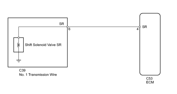
INSPECTION PROCEDURE
HINT:
Shift solenoid valve SR is turned ON/OFF normally when the shift lever is in D:
|
ECM gear shift command |
1st |
2nd |
3rd |
4th |
5th |
6th |
|
Shift solenoid valve SR |
ON |
ON |
ON |
ON |
OFF |
OFF |
PROCEDURE
|
1. |
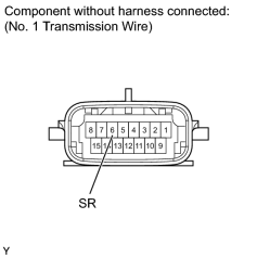
INSPECT NO. 1 TRANSMISSION WIRE (SHIFT SOLENOID VALVE SR) |
|
(a) Disconnect the C39 No. 1 transmission wire connector. |
(b) Measure the resistance according to the value(s) in the table below.
Standard Resistance:
|
Tester Connection |
Condition |
Specified Condition |
|---|---|---|
|
6 (SR) - Body ground |
20°C (68°F) |
11 to 15 Ω |
|

|
2. |
CHECK HARNESS AND CONNECTOR (NO. 1 TRANSMISSION WIRE - ECM) |
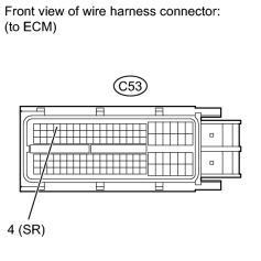
(a) Disconnect the C53 ECM connector.
(b) Measure the resistance according to the value(s) in the table below.
Standard Resistance:
|
Tester Connection |
Condition |
Specified Condition |
|---|---|---|
|
C53-4 (SR) - Body ground |
20°C (68°F) |
11 to 15 Ω |
|
|
3. |
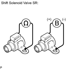
INSPECT SHIFT SOLENOID VALVE SR |
|
(a) Remove shift solenoid valve SR. |
(b) Measure the resistance according to the value(s) in the table below.
Standard Resistance:
|
Tester Connection |
Condition |
Specified Condition |
|---|---|---|
|
Shift solenoid valve SR connector terminal - Shift solenoid valve SR body |
20°C (68°F) |
11 to 15 Ω |
(c) Apply battery voltage (12 V) to the shift solenoid valve and check that the valve moves and makes an operating noise.
OK:
|
Measurement Condition |
Specified Condition |
|---|---|
|
Valve moves and makes an operating noise |
|

|

|