
- Engine switch on (IG)
- Shift lever in S, "+" or "-"
| Last Modified: 11-27-2007 | 1.6 J | |
| Service Category: Drivetrain | Section: Automatic Transmission/Transaxle | |
| Model Year: 2008 | Model: LX570 | Doc ID: RM000000WP102QX |
| Title: AB60F AUTOMATIC TRANSMISSION / TRANSAXLE: AUTOMATIC TRANSMISSION SYSTEM: DESCRIPTION (2008 LX570) | ||
|
Transmission Control Switch Circuit |
DESCRIPTION
When moving the shift lever to S using the transmission control switch, it is possible to switch the shift range between "1" (1st range) and "6" (6th range).
Shifting to "+" once raises the shift range by one, and shifting to "-" lowers the shift range by one.
WIRING DIAGRAM
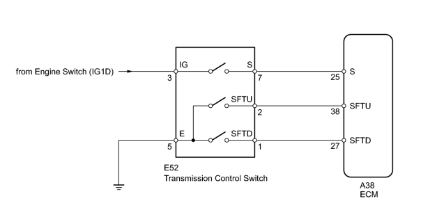
INSPECTION PROCEDURE
PROCEDURE
|
1. |
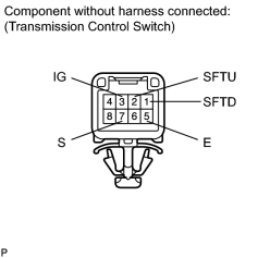
INSPECT TRANSMISSION CONTROL SWITCH |
|
(a) Disconnect the E52 transmission control switch connector. |
(b) Measure the resistance according to the value(s) in the table below.
Standard Resistance:
|
Tester Connection |
Condition |
Specified Condition |
|---|---|---|
|
3 (IG) - 7 (S) |
Shift lever in S, "+" or "-" |
Below 1 Ω |
|
2 (SFTU) - 5 (E) |
Shift lever held in "+" (Up-shift) |
Below 1 Ω |
|
1 (SFTD) - 5 (E) |
Shift lever held in "-" (Down-shift) |
Below 1 Ω |
|
3 (IG) - 7 (S) |
Shift lever not in S, "+" or "-" |
10 kΩ or higher |
|
2 (SFTU) - 5 (E) |
Shift lever in S |
10 kΩ or higher |
|
1 (SFTD) - 5 (E) |
Shift lever in S |
10 kΩ or higher |
|
|
2. |
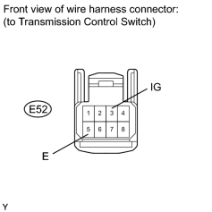
CHECK HARNESS AND CONNECTOR (TRANSMISSION CONTROL SWITCH - BATTERY, BODY GROUND) |
|
(a) Disconnect the E52 transmission control switch connector. |
(b) Measure the voltage according to the value(s) in the table below.
Standard Voltage:
|
Tester Connection |
Switch Condition |
Specified Condition |
|---|---|---|
|
E52-3 (IG) - Body ground |
Engine switch on (IG) |
11 to 14 V |
|
E52-3 (IG) - Body ground |
Engine switch off |
Below 1 V |
(c) Measure the resistance according to the value(s) in the table below.
Standard Resistance:
|
Tester Connection |
Condition |
Specified Condition |
|---|---|---|
|
E52-5 (E) - Body ground |
Always |
Below 1 Ω |
|
|
3. |
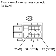
CHECK HARNESS AND CONNECTOR (TRANSMISSION CONTROL SWITCH - ECM) |
|
(a) Disconnect the A38 ECM connector. |
(b) Measure the voltage according to the value(s) in the table below.
Standard Voltage:
|
Tester Connection |
Condition |
Specified Condition |
|---|---|---|
|
A38-25 (S) - Body ground |
|
11 to 14 V |
|
A38-25 (S) - Body ground |
|
Below 1 V |
(c) Measure the resistance according to the value(s) in the table below.
Standard Resistance:
|
Tester Connection |
Condition |
Specified Condition |
|---|---|---|
|
A38-38 (SFTU) - Body ground |
|
Below 1 Ω |
|
A38-27 (SFTD) - Body ground |
|
Below 1 Ω |
|
A38-38 (SFTU) - Body ground |
|
10 kΩ or higher |
|
A38-27 (SFTD) - Body ground |
|
10 kΩ or higher |
|

|

|