| Last Modified: 11-27-2007 | 1.6 J | |
| Service Category: Vehicle Interior | Section: Heating/Air Conditioning | |
| Model Year: 2008 | Model: LX570 | Doc ID: RM000000XCQ01AX |
| Title: HEATING / AIR CONDITIONING: AIR CONDITIONING SYSTEM: DESCRIPTION (2008 LX570) | ||
|
Air Conditioning Compressor Magnetic Clutch Circuit |
DESCRIPTION
When the air conditioning amplifier assembly is turned on, a magnetic clutch on signal is sent from the MGC terminal of the air conditioning amplifier assembly. Then, the magnetic clutch relay turns on to operate the magnetic clutch.
WIRING DIAGRAM
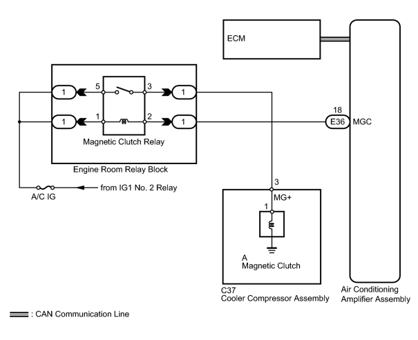
INSPECTION PROCEDURE
PROCEDURE
|
1. |
CHECK CAN COMMUNICATION SYSTEM |
(a) Check for CAN communication system DTCs related to the air conditioning system.
Result
|
Result |
Proceed to |
|---|---|
|
CAN DTC is not output |
A |
|
CAN DTC is output |
B |
|

|
2. |
READ VALUE USING TECHSTREAM (A/C SIGNAL) |
(a) Use the Data List to check if the A/C switch is functioning properly.
Engine
|
Tester Display |
Measurement Item/Range |
Normal Condition |
Diagnostic Note |
|---|---|---|---|
|
A/C Signal |
A/C switch signal / ON or OFF |
ON: A/C switch on OFF: A/C switch off |
- |
OK:
The display is as specified in the normal condition.
|
|
3. |
INSPECT FUSE (A/C IG) |
(a) Remove the A/C IG fuse from the cowl side junction block LH.
(b) Measure the resistance according to the value(s) in the table below.
Standard Resistance:
|
Tester Connection |
Condition |
Specified Condition |
|---|---|---|
|
A/C IG fuse |
Always |
Below 1 Ω |
|
|
4. |
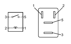
INSPECT MAGNETIC CLUTCH RELAY |
|
(a) Remove the magnetic clutch relay from the engine room relay block. |
(b) Measure the resistance according to the value(s) in the table below.
Standard Resistance:
|
Tester Connection |
Condition |
Specified Condition |
|---|---|---|
|
3 - 5 |
Battery voltage not applied to terminals 1 and 2 |
10 kΩ or higher |
|
3 - 5 |
Battery voltage applied to terminals 1 and 2 |
Below 1 Ω |
|
|
5. |
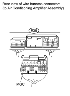
CHECK HARNESS AND CONNECTOR (AIR CONDITIONING AMPLIFIER - BATTERY) |
|
(a) Disconnect the E36 amplifier connector. |
(b) Measure the voltage according to the value(s) in the table below.
Standard Voltage:
|
Tester Connection |
Switch Condition |
Specified Condition |
|---|---|---|
|
E36-18 (MGC) - Body ground |
Engine switch off |
Below 1 V |
|
E36-18 (MGC) - Body ground |
Engine switch on (IG) |
11 to 14 V |
|
|
6. |
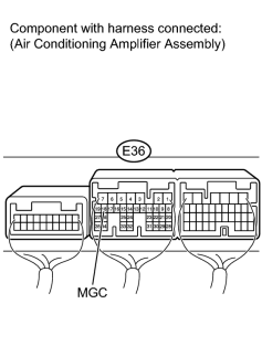
INSPECT AIR CONDITIONING AMPLIFIER ASSEMBLY |
|
(a) Reconnect the E36 amplifier connector. |
(b) Measure the voltage according to the value(s) in the table below.
Standard Voltage:
|
Tester Connection |
Switch Condition |
Specified Condition |
|---|---|---|
|
E36-18 (MGC) - Body ground |
Engine switch on (IG) A/C switch off |
11 to 14 V |
|
E36-18 (MGC) - Body ground |
Engine switch on (IG) A/C switch on |
Below 1 V |
|
|
7. |
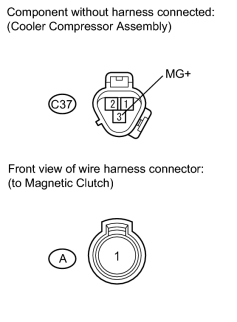
INSPECT COOLER COMPRESSOR ASSEMBLY |
|
(a) Disconnect the C37 compressor connector. |
(b) Disconnect the A magnetic clutch connector.
(c) Measure the resistance according to the value(s) in the table below.
Standard Resistance:
|
Tester Connection |
Condition |
Specified Condition |
|---|---|---|
|
C37-3 (MG+) - A-1 |
Always |
Below 1 Ω |
|
C37-3 (MG+) - Body ground |
Always |
10 kΩ or higher |
|
|
8. |
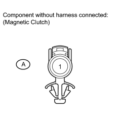
INSPECT MAGNETIC CLUTCH |
|
(a) Measure the resistance according to the value(s) in the table below. Standard Resistance:
|
(b) When connector terminal A-1 is connected to the positive (+) battery terminal, check that the following occurs: 1) the operating sound of the magnetic clutch can be heard, and 2) the hub and rotor of the magnetic clutch lock.
|
|
9. |
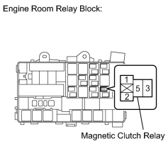
CHECK HARNESS AND CONNECTOR (ENGINE ROOM RELAY BLOCK - BATTERY) |
|
(a) Remove the magnetic clutch relay from the engine room relay block. |
(b) Measure the voltage according to the value(s) in the table below.
Standard Voltage:
|
Tester Connection |
Switch Condition |
Specified Condition |
|---|---|---|
|
Relay block magnetic clutch relay terminal 5 - Body ground |
Engine switch on (IG) |
11 to 14 V |
|
Relay block magnetic clutch relay terminal 1 - Body ground |
Engine switch on (IG) |
11 to 14 V |
|

|

|