- Signals between the main body ECU and combination meter are inconsistent.
| Last Modified: 11-27-2007 | 1.6 C | |
| Service Category: Vehicle Interior | Section: Theft Deterrent/Keyless Entry | |
| Model Year: 2008 | Model: LX570 | Doc ID: RM000000XEV032X |
| Title: THEFT DETERRENT / KEYLESS ENTRY: SMART ACCESS SYSTEM WITH PUSH-BUTTON START (for Start Function): DESCRIPTION (2008 LX570) | ||
|
DTC |
B2282 |
Vehicle Speed Signal Malfunction |
|
DTC |
B2283 |
Vehicle Speed Sensor Malfunction |
DESCRIPTION
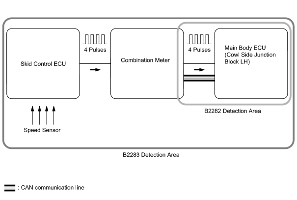
The main body ECU and the combination meter are connected with a cable and the CAN communication line. DTC B2282 is stored when signals, transmitted through the cable and communication line, do not match.
|
DTC Code |
Detection Condition |
Trouble Area |
|---|---|---|
|
B2282 |
When the following conditions are met:
|
|
The skid control ECU converts signals from the speed sensor into 4-pulse signals and sends them to the combination meter. After these signals are converted into a more precise rectangular waveform by the waveform shaping circuit inside the combination meter, they are then transmitted to the main body ECU. The main body ECU determines the vehicle speed based on the frequencies of these pulse signals.
|
DTC Code |
Detection Condition |
Trouble Area |
|---|---|---|
|
B2283 |
When both of the conditions below are met:
|
|
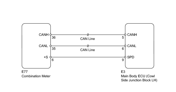
WIRING DIAGRAM
INSPECTION PROCEDURE
PROCEDURE
|
1. |
READ VALUE USING TECHSTREAM (VEHICLE SPEED SIGNAL) |
(a) Use the Data List to check if the vehicle speed signal is functioning properly.
Main Body
|
Tester Display |
Measurement Item/Range |
Normal Condition |
Diagnostic Note |
|---|---|---|---|
|
Vehicle Speed Signal |
Vehicle speed signal/Stop or Run |
Stop: Vehicle stopped Run: Vehicle running |
- |
Result
|
Result |
Proceed to |
|---|---|
|
Display on the Techstream does not change according to vehicle condition |
A |
|
Display on the Techstream changes according to vehicle condition |
B |
|

|
2. |
CHECK HARNESS AND CONNECTOR (MAIN BODY ECU - COMBINATION METER) |
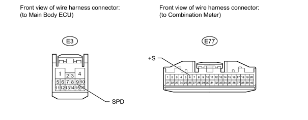
(a) Disconnect the E3 main body ECU connector.
(b) Disconnect the E77 combination meter connector.
(c) Measure the resistance according to the value(s) in the table below.
Standard Resistance:
|
Tester Connection |
Condition |
Specified Condition |
|---|---|---|
|
E3-9 (SPD) - E77-6 (+S) |
Always |
Below 1 Ω |
|
E3-9 (SPD) or E77-6 (+S) - Body ground |
Always |
10 kΩ or higher |
|
|
3. |
REPLACE MAIN BODY ECU (COWL SIDE JUNCTION BLOCK LH) |
(a) Temporarily replace the main body ECU with a new or normally functioning one.
(b) Check whether DTC B2282 and B2283 are output.
OK:
No DTC is output.
|

|

|