- Open or short in Camshaft Oil Control Valve (OCV) (for exhaust side of Bank 1) circuit
- OCV (for exhaust side of Bank 1)
- ECM
| Last Modified: 11-27-2007 | 1.6 C | |
| Service Category: Engine/Hybrid System | Section: Engine Control | |
| Model Year: 2008 | Model: LX570 | Doc ID: RM000000XH702XX |
| Title: 3UR-FE ENGINE CONTROL: SFI SYSTEM: DESCRIPTION (2008 LX570) | ||
|
DTC |
P0013 |
Camshaft Position "B" Actuator Circuit / Open (Bank 1) |
|
DTC |
P0023 |
Camshaft Position "B" Actuator Circuit / Open (Bank 2) |
DESCRIPTION
- This DTC is designed to detect opens or shorts in the Camshaft Oil Control Valve (OCV) circuit. If the OCV duty-cycle is excessively high or low while the engine is running, the ECM will illuminate the MIL and store the DTC.
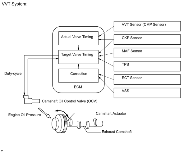
- The VVT (variable valve timing) system adjusts the intake valve timing to improve the driveability. The engine oil pressure turns the camshaft actuator to adjust the valve timing. The OCV is a solenoid valve and switches the engine oil line. The valve moves when the ECM applies 12 volts to the solenoid. The ECM changes the energizing time to the solenoid (duty-cycle) in accordance with the camshaft position, crankshaft position, throttle position, etc.
|
DTC Code |
DTC Detection Condition |
Trouble Area |
|---|---|---|
|
P0013 |
An open or short in the Camshaft Oil Control Valve (OCV) for exhaust side (for Bank 1) circuit (1 trip detection logic). |
|
|
P0023 |
An open or short in the OCV for exhaust side (for Bank 2) circuit (1 trip detection logic). |
|
MONITOR DESCRIPTION
This DTC is designed to detect opens or shorts in the camshaft oil control valve (OCV) circuit. If the OCV duty-cycle is excessively high or low while the engine is running, the ECM will illuminate the MIL and store the DTC.
MONITOR STRATEGY
|
Related DTCs |
P0013: Exhaust camshaft OCV (for Bank 1) P0023: Exhaust camshaft OCV (for Bank 2) |
|
Required sensors/Components (Main) |
Exhaust camshaft OCV |
|
Required sensors/Components (Related) |
- |
|
Frequency of operation |
Continuous |
|
Duration |
1 second |
|
MIL operation |
Immediate |
|
Sequence of operation |
None |
TYPICAL ENABLING CONDITIONS
|
Monitor runs whenever following DTCs not stored |
None |
|
All of following conditions met |
- |
|
Starter |
Off |
|
Engine switch |
On (IG) |
|
Time after engine switch off to on (IG) |
0.5 seconds or more |
TYPICAL MALFUNCTION THRESHOLDS
|
One of following conditions met |
- |
|
A. All of following conditions met |
- |
|
Battery voltage |
11 to 13 V |
|
Target duty ratio |
Less than 70% |
|
Output signal duty ratio |
100% |
|
B. All of following conditions met |
- |
|
Battery voltage |
13 V or higher |
|
Target duty ratio |
Less than 80% |
|
Output signal duty ratio |
100% |
|
C. Both of following conditions met |
- |
|
Current cut status |
Not cut |
|
Output signal duty ratio |
3% or less |
COMPONENT OPERATING RANGE
|
OCV duty-cycle |
4 to 100% when engine running |
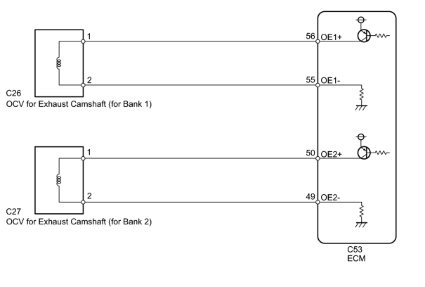
WIRING DIAGRAM
INSPECTION PROCEDURE
HINT:
- If DTC P0013 is output, check the bank 1 VVT system for exhaust side circuit.
- Bank 1 refers to the bank that includes the No. 1 cylinder.
- If DTC P0023 is output, check the bank 2 VVT system for exhaust side circuit.
- Bank 2 refers to the bank that does not include the No. 1 cylinder.
- Read freeze frame data using the Techstream. Freeze frame data records the engine condition when malfunctions are detected. When troubleshooting, freeze frame data can help determine if the vehicle was moving or stationary, if the engine was warmed up or not, if the air-fuel ratio was lean or rich, and other data from the time the malfunction occurred.
PROCEDURE
|
1. |
CHECK DTC (DTC P0013 OR P0023) |
(a) Connect the Techstream to the DLC3.
(b) Clear DTC after recording the freeze frame data and DTC.
(c) Turn the engine switch off.
(d) Allow the engine to idle and check DTC.
(e) Check that P0013 or P0023 is not output.
OK:
P0013 or P0023 is not output.
|

|
2. |
INSPECT CAMSHAFT OIL CONTROL VALVE ASSEMBLY |
|
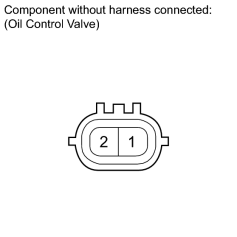
(a) Disconnect the C26 or C27 OCV connector. |
(b) Remove the camshaft oil control valve (OCV)
 .
.
(c) Measure the resistance according to the value(s) in the table below.
Standard Resistance:
|
Tester Connection |
Condition |
Specified Condition |
|---|---|---|
|
1 - 2 |
20°C (68°F) |
6.9 to 7.9 Ω |
|
|
3. |
CHECK HARNESS AND CONNECTOR (OCV - ECM) |
|
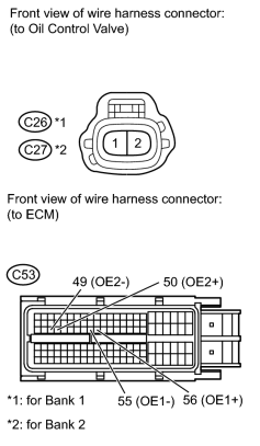
(a) Disconnect the C26 or C27 OCV connector. |
(b) Disconnect the C53 ECM connector.
(c) Measure the resistance according to the value(s) in the table below.
Standard Resistance:
|
Tester Connection |
Condition |
Specified Condition |
|---|---|---|
|
C26-1 - C53-56 (OE1+) |
Always |
Below 1 Ω |
|
C26-2 - C53-55 (OE1-) |
Always |
Below 1 Ω |
|
C27-1 - C53-50 (OE2+) |
Always |
Below 1 Ω |
|
C27-2 - C53-49 (OE2-) |
Always |
Below 1 Ω |
|
C26-1 or C53-56 (OE1+) - Body ground |
Always |
10 kΩ or higher |
|
C26-2 or C53-55 (OE1-) - Body ground |
Always |
10 kΩ or higher |
|
C27-1 or C53-50 (OE2+) - Body ground |
Always |
10 kΩ or higher |
|
C27-2 or C53-49 (OE2-) - Body ground |
Always |
10 kΩ or higher |
|

|

|