| Last Modified: 11-27-2007 | 1.6 J | |
| Service Category: Vehicle Exterior | Section: Window/Glass | |
| Model Year: 2008 | Model: LX570 | Doc ID: RM000000XI0013X |
| Title: WINDOW / GLASS: POWER WINDOW CONTROL SYSTEM: DESCRIPTION (2008 LX570) | ||
|
Front Passenger Side Power Window does not Operate with Front Passenger Side Power Window Switch |
DESCRIPTION
If the manual up/down function does not operate, there may be a malfunction in the power window regulator switch, front power window regulator motor RH, harness or connector.
WIRING DIAGRAM

INSPECTION PROCEDURE
PROCEDURE
|
1. |
CHECK LIN COMMUNICATION SYSTEM |
(a) Check for LIN communication system DTCs related to the power window control system
 .
.
OK:
LIN communication system DTCs are not output.
|

|
2. |
CHECK FOR DTC (B2312) |
(a) Check if DTC B2312 is output
.
OK:
DTC B2312 is not output.
|
|
3. |
READ VALUE USING TECHSTREAM (FRONT POWER WINDOW REGULATOR MOTOR RH) |
(a) Use the Data List to check if the power window regulator motor is functioning properly
.
P-Door Motor
|
Tester Display |
Measurement Item/Range |
Normal Condition |
Diagnostic Note |
|---|---|---|---|
|
P Door P/W Up SW |
Front passenger side power window manual up signal / ON or OFF |
ON: Front passenger side power window manual up switch operated OFF: Power window regulator switch not operated |
- |
|
P Door P/W Down SW |
Front passenger side power window manual down signal / ON or OFF |
ON: Front passenger side power window manual down switch operated OFF: Power window regulator switch not operated |
- |
OK:
Techstream display changes according to operation of power window regulator switch.
|
|
4. |
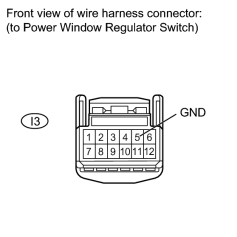
CHECK HARNESS AND CONNECTOR (POWER WINDOW REGULATOR SWITCH - BODY GROUND) |
|
(a) Disconnect the I3 switch connector. |
(b) Measure the resistance according to the value(s) in the table below.
Standard Resistance:
|
Tester Connection |
Condition |
Specified Condition |
|---|---|---|
|
I3-5 (GND) - Body ground |
Always |
Below 1 Ω |
|
|
5. |
CHECK HARNESS AND CONNECTOR (FRONT POWER WINDOW REGULATOR MOTOR RH - BATTERY AND BODY GROUND) |
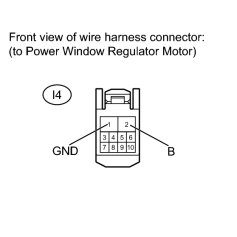
(a) Disconnect the I4 motor connector.
(b) Measure the voltage and resistance according to the value(s) in the table below.
Standard Voltage:
|
Tester Connection |
Condition |
Specified Condition |
|---|---|---|
|
I4-2 (B) - Body ground |
Always |
11 to 14 V |
Standard Resistance:
|
Tester Connection |
Condition |
Specified Condition |
|---|---|---|
|
I4-1 (GND) - Body ground |
Always |
Below 1 Ω |
|
|
6. |
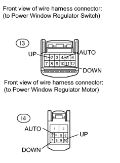
CHECK HARNESS AND CONNECTOR (POWER WINDOW REGULATOR SWITCH - FRONT POWER WINDOW REGULATOR MOTOR RH) |
|
(a) Disconnect the I3 switch connector. |
(b) Disconnect the I4 motor connector.
(c) Measure the resistance according to the value(s) in the table below.
Standard Resistance:
|
Tester Connection |
Condition |
Specified Condition |
|---|---|---|
|
I3-2 (UP) - I4-10 (UP) |
Always |
Below 1 Ω |
|
I3-10 (DOWN) - I4-7 (DOWN) |
Always |
Below 1 Ω |
|
I3-4 (AUTO) - I4-4 (AUTO) |
Always |
Below 1 Ω |
|
I3-2 (UP) or I4-10 (UP) - Body ground |
Always |
10 kΩ or higher |
|
I3-10 (DOWN) or I4-7 (DOWN) - Body ground |
Always |
10 kΩ or higher |
|
I3-4 (AUTO) or I4-4 (AUTO) - Body ground |
Always |
10 kΩ or higher |
|
|
7. |
INSPECT POWER WINDOW REGULATOR SWITCH |
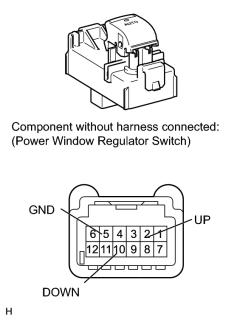
(a) Remove the power window regulator switch
.
(b) Measure the resistance according to the value(s) in the table below.
Standard Resistance:
|
Tester Connection |
Switch Condition |
Specified Condition |
|---|---|---|
|
I3-2 (UP) - I3-5 (GND) |
Manual up operation |
Below 1 Ω |
|
I3-10 (DOWN) - I3-5 (GND) |
Manual down operation |
Below 1 Ω |
|

|

|