| Last Modified: 11-27-2007 | 1.6 J | |
| Service Category: Suspension | Section: Tire Pressure Monitoring | |
| Model Year: 2008 | Model: LX570 | Doc ID: RM000000XN2026X |
| Title: TIRE PRESSURE MONITORING: TIRE PRESSURE WARNING SYSTEM: DESCRIPTION (2008 LX570) | ||
|
ECU Power Source Circuit |
DESCRIPTION
This is the power source for the tire pressure warning ECU.
WIRING DIAGRAM
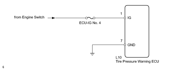
INSPECTION PROCEDURE
NOTICE:
- When replacing the tire pressure warning ECU, read the IDs stored in the old ECU using the Techstream and write them down before removal.
-
It is necessary to perform initialization
 after registration
of the transmitter IDs into the tire pressure warning ECU after the ECU and/or the tire pressure warning valve and transmitter has been replaced.
after registration
of the transmitter IDs into the tire pressure warning ECU after the ECU and/or the tire pressure warning valve and transmitter has been replaced.
PROCEDURE
|
1. |
INSPECT FUSE (ECU-IG NO. 4) |
(a) Remove the ECU-IG No. 4 fuse from the cowl side junction block RH.
(b) Measure the resistance according to the value(s) in the table below.
Standard Resistance:
|
Tester Connection |
Condition |
Specified Condition |
|---|---|---|
|
ECU-IG No. 4 fuse |
Always |
Below 1 Ω |
|

|
2. |
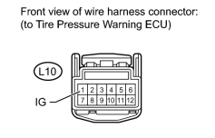
CHECK HARNESS AND CONNECTOR (ECU - BATTERY) |
|
(a) Disconnect the L10 ECU connector. |
(b) Measure the voltage according to the value(s) in the table below.
Standard Voltage:
|
Tester Connection |
Switch Condition |
Specified Condition |
|---|---|---|
|
L10-1 (IG) - Body ground |
Engine switch on (IG) |
11 to 14 V |
|
Engine switch off |
Below 1 V |
|
|
3. |
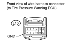
CHECK HARNESS AND CONNECTOR (ECU - BODY GROUND) |
|
(a) Disconnect the L10 ECU connector. |
(b) Measure the resistance according to the value(s) in the table below.
Standard Resistance:
|
Tester Connection |
Condition |
Specified Condition |
|---|---|---|
|
L10-7 (GND) - Body ground |
Always |
Below 1 Ω |
|
|
4. |
CHECK HARNESS AND CONNECTOR (ECU - FUSE) |
|
|
(a) Disconnect the L10 ECU connector. |
(b) Measure the resistance according to the value(s) in the table below.
Standard Resistance:
|
Tester Connection |
Condition |
Specified Condition |
|---|---|---|
|
L10-1 (IG) - Body ground |
Always |
10 kΩ or higher |
|

|

|